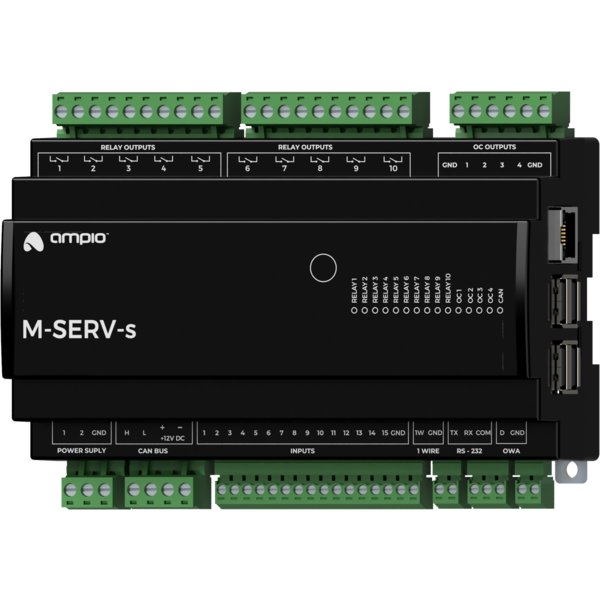
The image above is for illustration purpose only. The actual module may vary from the one presented here.
Module M-SERV-s is a component of the Ampio system. Required voltage to power the module is 11 — 16V DC. The module is controlled via CAN bus.
The M-SERV-s module is a communication gateway for Ampio mobile applications - both within the local network and via the Ampio Cloud platform - and it enables IP integrations. It also has fourteen ground-detecting inputs, ten relay outputs, four OC outputs (with RGBW lighting controller capabilities), and 1-Wire and RS-232 interfaces. The device can also be used as an OWA lighting bus controller and a multi-zone temperature controller. Moreover, it enables redundant power supply of the building automation bus through two independent power supplies.
Early revisions of M-SERV-s modules with a PCB number lower than 9, instead of ground-detecting inputs, were equipped with 14 supply voltage detecting inputs.
The Ampio UNI mobile application enables control over the building automation installation via smartphones and tablets. It also allows the end user to define and run scenes and implement simple automation rules.
The Ampio UNI mobile application makes it possible to connect to a home automation installation remotely, via the Ampio Cloud platform, and locally using a LAN. Users who do not want to utilise the Ampio Cloud platform can still use the application within the local area network.
In order to ensure smooth access to building automation installations, there is a limit on the number of simultaneous active connections to the installation via Ampio Cloud. A maximum of 6 users can connect remotely to the installation at the same time, of which a maximum of 3 profiles can be used for the connection of monitoring systems.
With the use of the module, it is possible to integrate devices and services that provide integration interfaces within the computer network. Integration rules are implemented in the Node-RED open source platform that allows for the definition of information flows and processing diagrams.
In the Node-RED environment, interaction with external devices and services can be accomplished in a number of ways. A technologically skilled user can carry on integrations based on basic communication interfaces, such as HTTP API or MQTT. There is also a possibility to use ready-made integration blocks developed by the Node-RED project community.
The Node-RED environment is available to both the installer and the end user. Integrations implemented with its use may apply to devices from other manufacturers, as well as services available in the network. There is also an option, for example, to send SMS messages using GSM gateway services, or display information on stock exchange quotations or weather forecasts on touch panels.
At the device configuration stage, it is also possible to implement simple IP integration rules through the Ampio Designer software.
The device includes an SIP server intended for integration with intercoms supporting the VoIP technology. When properly configured, it allows one to receive intercom calls on smartphones or tablets. It is also possible to configure an external VoIP service provider, thanks to which receiving calls from intercoms or other integrated VoIP devices will also be feasible from outside the local network.
The M-SERV-s module also defines its internal telephone number intended for invoking actions
via VoIP connection. At the device configuration stage, one can define the reaction of the
building automation system to specific sequences of numbers and characters * and #, sent to the
device during a VoIP call with the above-mentioned number.
In addition to the described features, the device also supports the following functionalities:
The module has inputs that go into the active state when they are shorted to ground. They can be used in the case of any devices with potential-free contact outputs, e.g. wall switches, reed switches, buttons, switches, etc. They can also be used for integration with devices with potential-free relay outputs or optocoupler outputs with a collector voltage greater than 12V.
Early revisions of M-SERV-s modules with a PCB number lower than 9, instead of ground-detecting inputs, were equipped with 14 supply voltage detecting inputs. If one need to connect a newer module to an installation prepared for an older one, it is needed to modify the connection method. Refer to the connection diagram to determine the nature of the required modifications.
The module has inputs that go into an active state when they are shorted to voltage in the range of 2-24 V DC. They can be used with any devices with potential-free contact outputs, e.g. wall switches, reed switches, buttons, switches, etc. They can also be used for integration with devices with potential-free relay outputs or optocoupler outputs with an isolated emitter.
Supply voltage detecting input is marked with number 15.
The module has relay outputs that enable switching on resistive and inductive loads. The module relays are normally open. The table below shows the permissible operating parameters of the relays depending on the nature of the load.
| The nature of the load | Maximum supply voltage | Maximum long-term permissible current |
|---|---|---|
| AC1: Resistive or moderately inductive AC loads | 250V AC | 10A |
| AC15: Inductive AC loads | 250V AC | 1.5A |
| DC1: Resistive or moderately inductive DC loads | 30V DC | 10A |
| DC13: Inductive DC loads | 30V DC | 2.5A |
The module outputs are not intended for controlling sockets due to the possibility of connecting a receiver that exceeds the current capacity of the module. It is possible to connect the module to a socket after connecting it to an external contactor.
As part of the module configuration, it is possible to activate the functionality of a roller shutter and a blind drives' controller. This mode is intended for the control of devices powered by electric motors with a variable direction of movement and a limited movement range. For example, roller shutters and blinds' drives. However, this mode can also be used in other devices of a similar nature, such as, e.g. gates.
In the controller mode for roller shutters and blinds' drives, pairs of the device’s relay outputs work as a single compound output dedicated to controlling a single connected device.
The controller mode for roller shutters and blinds' drive is designed to control devices with built-in limit switches that disconnect the drive’s power supply when the ends of the range of motion are reached.
In the primary operation mode of the relay outputs, they are controlled by switching on or off individual outputs. In the case of pairs of relays operating in the roller shutters and blinds' drive controller mode, the control is performed by closing and opening commands or by setting the opening level. When it comes to blinds, it is also possible to set the position of slats.
During operation, the module estimates the state of the controlled device, i.e. the degree of opening and the position of slats (if applicable). This information is available within the building automation bus and is used internally to perform control in terms of the degree of opening or deflection angle of the slats.
A single pair of relays operating in a controller mode for roller shutters and blinds' drives can only be connected to a single drive. Any other connection may result in incorrect operation of the device, as well as permanent damage to both, the module and the drive.
As part of the module’s configuration, a selection is made of which pairs of relay outputs are to support the discussed functionality.
The module has open-collector outputs allowing for smooth control of resistive loads supplied with voltage of up to 40V DC. It is also allowed to control loads of moderate inductive nature, in particular relays. Control is performed by the method of pulse-width modulation (PWM). Internally, each of the outputs allows the connected line to be short-circuited to the module’s ground.
As part of the module’s configuration, it is possible to activate the functionality of the RGBW lighting controller. Nominally, each of the open-collector outputs is controlled independently. When the functionality is activated, the control is done by defining the colour and intensity of the light.
The module allows the integration of devices equipped with an RS-232 communication interface with the Ampio building automation system. Depending on the integrated device, at the configuration stage, the appropriate interface operation mode should be selected. The following list presents possible variants:
The module has two inputs for 11 — 16V DC power supplies. The voltage supplied by the power supplies is used to power the CAN bus connected to the device. Failure of one of the power supplies does not affect the other power supply to the bus. In order to use the functionality properly, it is necessary to ensure that each power supply is able to power the CAN bus on its own.
As part of the device, the voltage supplied by each of the power supplies is measured - the measurement result is made available in the building automation bus.
The OWA lighting bus (One Wire Ampio) is a solution dedicated to controlling LED lighting. Each bus segment contains a controller and up to 16 lighting node drivers or LED lamps with integrated drivers. From the controller level, it is possible to smoothly adjust the brightness of light sources connected to each of the controllers. It is possible to control sets of light points or individual lights independently. It is also possible to implement the so-called staircase effect, i.e. smooth brightening and dimming of consecutive light points along the stairs, driveway, etc.
The OWA lighting bus consists of two wires - a ground wire and a wire that ensures communication between the controller and the drivers of a lighting node. Lighting node drivers also require a power line, hence the OWA bus is usually run with a three-wire cable.
With the use of several power lines, it is possible to connect to a single segment of the OWA bus lighting node drivers powered by different voltages. In such a case, however, care should be taken to properly equalise the ground potentials of each of the power supplies, i.e. to connect the grounding of the power supplies.
The module allows for the implementation of temperature control logic. Regulation is performed independently for a number of defined zones.
Within each zone, a temperature sensor is recognised, which determines the zone’s current temperature. The selection is made from sensors connected to any of the Ampio modules equipped with a 1-Wire interface, or sensors that are integrated into the building automation system in any other way, for example, via integration modules.
One or more heating or cooling devices are associated with each zone. Interaction with devices is performed by any output or integration module present in the building automation bus.
The temperature control set value can be determined by the end user manually via the mobile app or via Ampio touch panels. Through the mobile application, the user also has the option of defining time schedules that specify the expected temperature of each zone in time.
For each zone, two specific temperature values are also defined - comfortable and economical. Switching the controller set point value to one of the temperatures mentioned above can be quickly triggered by any other building automation device, e.g. by pressing a touch panel’s field. The values of these temperatures are defined by the end user and may also be used as a part of schedule definitions.
The operation of defined heaters and coolers is controlled on the basis of the measured value of the control zone’s current temperature and the current set value. The process can be governed by the following control algorithms:
The module has 8 temperature control zones, expandable to 32.
The module is equipped with a 1-Wire interface connector that allows to connect up to 6 digital Dallas DS18B20 temperature sensors. The temperature measurement result is available for all devices operating within the building automation bus. It may turn out to be particularly useful for purposes related to temperature regulation, or to present the measurement result on touch panels and in a mobile application.
The total length of the 1-Wire bus cable to which the temperature sensors are connected cannot exceed 15m.
The module is designed for mounting on a 35mm DIN rail. The module’s width is 160mm, 9 spaces/modules in DB. In order to start the module, it must be connected to the CAN bus. The bus of the Ampio system consists of four wires - two for power and two for communication between the modules.
In addition to the CAN bus interface, the device has eight connectors with screw terminals. They facilitate the connection of:
In order to connect to an external device using the RS-232 interface, one must prepare a cable terminated with a connector suitable for the device that is being integrated. The device connection diagram presents a variant of such a connection with a short circuit of the DCD, DTR and DSR lines. Before integration, read the manual of the integrated device to see, if the connection is required by it.
When using the open-collector outputs functionality, it should be borne in mind that the supply circuits of the connected loads are closed by the mass of the module. Therefore, it should be ensured that the mass of the device is connected to the mass of the power supply with a cable of appropriate thickness.
If the current consumed by all loads connected to the open-collector output is lower than 16A, it is sufficient to connect one ground terminal to the external power supply. With two terminals connected, the maximum current is 32A.
On the right side surface of the module there are connectors for the Ethernet interface and USB connectors. Connecting the device to the Internet is a prerequisite for using the device’s IP functionality.
On the right side of the module, there is an Ethernet connector to which one should connect a network cable terminated with an RJ-45 connector. This should be taken into account when planning the electrical distribution board’s layout.
On the front of the module there are signalling LED indicators. The green LED with the label CAN indicates the status of communication on the CAN bus:
Apart from the diode that indicates the status of the communication bus, there are fourteen red diodes on the front of the device indicating the status of the relay outputs and the open-collector.
The module is programmed with the use of the Ampio Designer software. It allows you to modify the parameters of the module and define its behaviour in response to signals directly available to the module as well as general information coming from all devices present in the home automation bus.
If the functionality of the roller shutters and blinds' drives controller is used, each connected device should be calibrated. The calibration is performed by defining the time parameters of full opening and closing, and the time parameters of the rotation of slats of the blinds (if applicable).
In addition, a part of the device’s configuration is carried out through communication within the local network using the Ampio Designer software.
The Ampio Designer software allows one to define the user interface of the building automation installation available in the mobile application. The interface is built by defining views, which contain widgets that present information about the state of the installation and allow the user to interact with it. The application also allows to implement simple IP integrations with the use of the actions mechanism.
The device provides a configuration utility accessible through a web browser. After logging in to the utility, basic information about the device is available. It is also possible to configure the IP connection and network services provided by the device.
The M-SERV-s module broadcasts information about the current time in the automation bus every full minute. The rest of the system’s devices listen to this information only when their configuration includes time-dependent conditions.
In a situation where a time-dependent configuration is uploaded into a device without internal information about the current time, the information from the M-RT-s will be interpreted by this device only at the next full minute and only then it will be possible to evaluate the time condition.
The described specificity of operation does not have any impact on the functioning of the system during its normal operation, but it may lead to the erroneous impression that the condition does not work during programming.
In order to use the configuration tools communicating with the module within the local network, it is necessary to know its IP address. Modules from the M-SERV family that are equipped with a screen will have their IP address displayed there.
The M-SERV-s module also broadcasts its IP address via the mDNS protocol - in the case of
client devices that support this technology, the module will be available under the ampio.local
domain name.
After proper configuration of the computer’s network interface, each module from the M-SERV family is
also visible at the address 10.76.100.100 in the network with the mask 255.255.255.0. However,
this address cannot be used when there is more than one such module within one local network.
The IP address of the device can also be found on the display on the module’s front.
In order to implement network functionalities, the M-SERV-s device can establish network connections with a number of services available on the Internet. For typical network environment configurations, no additional actions should be required. However, if the device is to operate in a more restrictive environment, such as corporate networks or other networks with a strict firewall configuration, it may be necessary to explicitly allow the device to make the required connection. To do this, it is useful to refer to a list of destination ports with which the device connects.
| Port | Protocol | Comment |
|---|---|---|
| 443 | TCP | Ampio Cloud, software updated, Node-RED |
| 7143 | TCP | Ampio Cloud |
| 4040 | TCP | Ampio Cloud |
| 7030 | TCP | Remote support, Ampio Cloud (legacy) |
| 7031 | TCP | Remote support |
| 3478 | TCP/UDP | Ampio Cloud |
| 5349 | TCP/UDP | Ampio Cloud |
The M-SERV-s device provides considerable freedom in terms of implementing custom IP integrations, especially using the Node-RED platform. Such integrations may imply that the device establishes further connections, other than those mentioned above. The characteristics of such connections depend on a specific integration and are beyond the scope of this document.
On the first launch of the device, it must be initialised. The initialisation consists of defining data for the server access - server network services are not available until strong passwords of system users are established. After setting up the passwords, the device is restarted. During the reboot, configuration activities that may take up to 15 minutes are performed.
Initialisation of the device is also necessary after updating the server software - after setting up passwords and completing configuration activities, it is possible to upload configuration copies created before the update.
The software and configuration related to the implementation of the module’s IP functionality are stored on an SD card. However, moving the SD card from one device to another is not a correct way to transfer data between them. When M-SERV class modules start operating with an SD card that they do not recognise, an initialisation procedure is launched, during which the device’s configuration is restored to its factory settings.
Moving an SD card from one M-SERV class device to another results in the deletion of the configuration saved on the card!
In order to transfer data, use the option of data import and export of appropriate configuration and integration tools. The backup option available in the Ampio Designer software allows one to store the configuration of the Node-RED platform, the configuration of the mobile application, as well as messages and automations created by the system user.
Industrial-grade SD cards (usually marked with the word ‘industrial’) should be used with modules from the M-SERV family.
When connecting external storage to a USB port, you should take the server’s power capacity into account. Drives that draw more than 150mA should be powered externally, for example via an active USB hub.
Dimensions expressed in millimeters.
 Click to enlarge and open in a new tab.
Instructions on how to connect the OWA lighting bus are available in the documentation of the lighting node drivers and LED lamps with integrated drivers.
