The image above is for illustration purpose only. The actual module may vary from the one presented here.
* The LoRa interface requires a communication adapter and an external antenna to be attached.
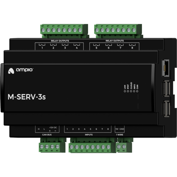
Module M-SERV-3s is a component of the Ampio system. Required voltage to power the module is 11 — 16V DC. The module is controlled via CAN bus.
The M-SERV-3s module is a communication gateway for Ampio mobile applications - both within the local network and via the Ampio Cloud platform - plus, it enables IP integrations. It also has eight voltage-detecting inputs, eight relay outputs and a 1-Wire interface.
The device can also act as a base station for the Ampio LoRa interface, which is necessary when using Ampio wireless modules from the WL group in the building automation installation.
The Ampio UNI mobile application enables control over the building automation installation via smartphones and tablets. It also allows the end user to define and run scenes and implement simple automation rules.
The Ampio UNI mobile application makes it possible to connect to a home automation installation remotely, via the Ampio Cloud platform, and locally using a LAN. Users who do not want to utilise the Ampio Cloud platform can still use the application within the local area network.
In order to ensure smooth access to building automation installations, there is a limit on the number of simultaneous active connections to the installation via Ampio Cloud. A maximum of 6 users can connect remotely to the installation at the same time, of which a maximum of 3 profiles can be used for the connection of monitoring systems.
With the use of the module, it is possible to integrate devices and services that provide integration interfaces within the computer network. Integration rules are implemented in the Node-RED open source platform that allows for the definition of information flows and processing diagrams.
In the Node-RED environment, interaction with external devices and services can be accomplished in a number of ways. A technologically skilled user can carry on integrations based on basic communication interfaces, such as HTTP API or MQTT. There is also a possibility to use ready-made integration blocks developed by the Node-RED project community.
The Node-RED environment is available to both the installer and the end user. Integrations implemented with its use may apply to devices from other manufacturers, as well as services available in the network. There is also an option, for example, to send SMS messages using GSM gateway services, or display information on stock exchange quotations or weather forecasts on touch panels.
At the device configuration stage, it is also possible to implement simple IP integration rules through the Ampio Designer software.
The device includes an SIP server intended for integration with intercoms supporting the VoIP technology. When properly configured, it allows one to receive intercom calls on smartphones or tablets. It is also possible to configure an external VoIP service provider, thanks to which receiving calls from intercoms or other integrated VoIP devices will also be feasible from outside the local network.
The M-SERV-3s module also defines its internal telephone number intended for invoking actions
via VoIP connection. At the device configuration stage, one can define the reaction of the
building automation system to specific sequences of numbers and characters * and #, sent to the
device during a VoIP call with the above-mentioned number.
In addition to the described features, the device also supports the following functionalities:
The module has relay outputs that enable switching on resistive and inductive loads. The module relays are normally open. The table below shows the permissible operating parameters of the relays depending on the nature of the load.
| The nature of the load | Maximum supply voltage | Maximum long-term permissible current |
|---|---|---|
| AC1: Resistive or moderately inductive AC loads | 250V AC | 10A |
| AC15: Inductive AC loads | 250V AC | 1.5A |
| DC1: Resistive or moderately inductive DC loads | 30V DC | 10A |
| DC13: Inductive DC loads | 30V DC | 2.5A |
The module has inputs that go into an active state when they are shorted to voltage in the range of 2-24 V DC. They can be used with any devices with potential-free contact outputs, e.g. wall switches, reed switches, buttons, switches, etc. They can also be used for integration with devices with potential-free relay outputs or optocoupler outputs with an isolated emitter.
The module is equipped with a 1-Wire interface connector that allows to connect up to 6 digital Dallas DS18B20 temperature sensors. The temperature measurement result is available for all devices operating within the building automation bus. It may turn out to be particularly useful for purposes related to temperature regulation, or to present the measurement result on touch panels and in a mobile application.
The total length of the 1-Wire bus cable to which the temperature sensors are connected cannot exceed 15m.
The device acts as a base station for the Ampio devices from the WL group that communicate via the Ampio LoRa wireless interface. As a base station, the device distributes information between wireless modules and other building automation devices.
As part of installation activities, each Ampio LoRa device must be paired with a module that acts as a base station. To do this, use the Ampio Designer software to enter the M-SERV-3s module into a search mode for modules from the WL group. When the search mode is active, press the pairing button on the wireless module that you are trying to pair three times. If the operation is successful, the found device will appear on the list of paired wireless modules within the Ampio Designer software.
The module is designed for mounting on a 35mm DIN rail. The module’s width is 140mm, 8 spaces/modules in DB. In order to start the module, it must be connected to the CAN bus. The bus of the Ampio system consists of four wires - two for power and two for communication between the modules.
In addition to the CAN bus interface, the device has four connectors with screw terminals. They allow for the connection of eight signal lines to ground detecting inputs, eight loads to relay outputs, and up to 6 digital Dallas DS18B20 temperature sensors.
On the right side of the module, there are connectors for an Ethernet interface and USB connectors. Connecting the device to the Internet is necessary in order to use the device’s IP functionality.
On the right side of the module there is an Ethernet connector, to which one should connect a network cable terminated with an RJ-45 connector. This should be taken into account when planning the electrical distribution board’s layout.
In order to take advantage of the functionality of the Ampio LoRa base station, it is necessary to install a LoRa adapter and its antenna. In order to mount the assembly, it is necessary to remove the front part of the module’s casing and make a mounting hole.
Never open the module’s casing when it is connected to the CAN network or its relay or OC outputs are connected to any power sources!
The LoRa adapter has an SMA antenna connector and a 4-pin connector for connecting the adapter to the M-SERV-3s module’s main board. The connection is made using a cable delivered with the module. The location of the connector on the module’s main board is shown in the figure below.
 Click to enlarge and open in a new tab.
The next step is to make a mounting hole through which the SMA antenna connector of the LoRa adapter will be led outside the device housing. The hole should be drilled with a ⌀7mm drill bit. After making the hole, the SMA connector should be led through it and secured with a washer and a nut. The location of the mounting hole is not imposed - the hole can be located in any convenient place. However, care should be taken to ensure that the LoRa adapter and other components still fit nicely inside the device’s casing after reassembly.
The LoRa antenna can be connected to the connector directly or via a coaxial cable with an impedance of 50Ω. In the case of direct installation and the use of a distribution board cover made of conductive material, it should be made sure that the antenna is located outside of the cover.
On the front of the module there are signalling LED indicators. The green LED with the label CAN indicates the status of communication on the CAN bus:
Apart from the communication bus status LED, there are four red LEDs on the front of the device:
The module is programmed with a special programmer, available for authorised technicians, and the Ampio Smart Home CAN configurator software. It allows you to modify the parameters of the module and define its behaviour in response to signals directly available to the module as well as general information coming from all devices present in the home automation bus.
In addition, a part of the device’s configuration is carried out through communication within the local network using the Ampio Designer software.
The Ampio Designer software allows one to define the user interface of the building automation installation available in the mobile application. The interface is built by defining views, which contain widgets that present information about the state of the installation and allow the user to interact with it. The application also allows to implement simple IP integrations with the use of the actions mechanism.
The device provides a configuration utility accessible through a web browser. After logging in to the utility, basic information about the device is available. It is also possible to configure the IP connection and network services provided by the device.
The M-SERV-3s module broadcasts information about the current time in the automation bus every full minute. The rest of the system’s devices listen to this information only when their configuration includes time-dependent conditions.
In a situation where a time-dependent configuration is uploaded into a device without internal information about the current time, the information from the M-RT-s will be interpreted by this device only at the next full minute and only then it will be possible to evaluate the time condition.
The described specificity of operation does not have any impact on the functioning of the system during its normal operation, but it may lead to the erroneous impression that the condition does not work during programming.
In order to use the configuration tools communicating with the module within the local network, it is necessary to know its IP address. Modules from the M-SERV family that are equipped with a screen will have their IP address displayed there.
The M-SERV-3s module also broadcasts its IP address via the mDNS protocol - in the case of
client devices that support this technology, the module will be available under the ampio.local
domain name.
After proper configuration of the computer’s network interface, each module from the M-SERV family is
also visible at the address 10.76.100.100 in the network with the mask 255.255.255.0. However,
this address cannot be used when there is more than one such module within one local network.
In order to implement network functionalities, the M-SERV-3s device can establish network connections with a number of services available on the Internet. For typical network environment configurations, no additional actions should be required. However, if the device is to operate in a more restrictive environment, such as corporate networks or other networks with a strict firewall configuration, it may be necessary to explicitly allow the device to make the required connection. To do this, it is useful to refer to a list of destination ports with which the device connects.
| Port | Protocol | Comment |
|---|---|---|
| 443 | TCP | Ampio Cloud, software updated, Node-RED |
| 7143 | TCP | Ampio Cloud |
| 4040 | TCP | Ampio Cloud |
| 7030 | TCP | Remote support, Ampio Cloud (legacy) |
| 7031 | TCP | Remote support |
| 3478 | TCP/UDP | Ampio Cloud |
| 5349 | TCP/UDP | Ampio Cloud |
The M-SERV-s device provides considerable freedom in terms of implementing custom IP integrations, especially using the Node-RED platform. Such integrations may imply that the device establishes further connections, other than those mentioned above. The characteristics of such connections depend on a specific integration and are beyond the scope of this document.
On the first launch of the device, it must be initialised. The initialisation consists of defining data for the server access - server network services are not available until strong passwords of system users are established. After setting up the passwords, the device is restarted. During the reboot, configuration activities that may take up to 15 minutes are performed.
Initialisation of the device is also necessary after updating the server software - after setting up passwords and completing configuration activities, it is possible to upload configuration copies created before the update.
The software and configuration related to the implementation of the module’s IP functionality are stored on an SD card. However, moving the SD card from one device to another is not a correct way to transfer data between them. When M-SERV class modules start operating with an SD card that they do not recognise, an initialisation procedure is launched, during which the device’s configuration is restored to its factory settings.
Moving an SD card from one M-SERV class device to another results in the deletion of the configuration saved on the card!
In order to transfer data, use the option of data import and export of appropriate configuration and integration tools. The backup option available in the Ampio Designer software allows one to store the configuration of the Node-RED platform, the configuration of the mobile application, as well as messages and automations created by the system user.
Industrial-grade SD cards (usually marked with the word ‘industrial’) should be used with modules from the M-SERV family.
When connecting external storage to a USB port, you should take the server’s power capacity into account. Drives that draw more than 150mA should be powered externally, for example via an active USB hub.
Dimensions expressed in millimeters.
 Click to enlarge and open in a new tab.
