The image above is for illustration purpose only. The actual module may vary from the one presented here.
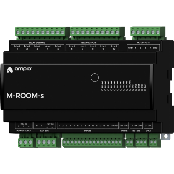
Module M-ROOM-s is a component of the Ampio system. Required voltage to power the module is 11 — 16V DC. The module is controlled via CAN bus.
The module can provide many of the functionalities envisioned by the Ampio building automation system’s architecture. As such, it is intended as a single device that allows to cover most of the needs of installations found in small houses, apartments or hotel rooms.
This document describes all the functionalities that can be implemented in the device. The M-ROOM-s module is available by special order, in which the module’s custom functionalities are specified.
Early revisions of M-ROOM-s modules with a PCB number lower than 2, instead of ground-detecting inputs, were equipped with 14 supply voltage detecting inputs.
The module has inputs that go into the active state when they are shorted to ground. They can be used in the case of any devices with potential-free contact outputs, e.g. wall switches, reed switches, buttons, switches, etc. They can also be used for integration with devices with potential-free relay outputs or optocoupler outputs with a collector voltage greater than 12V.
Early revisions of M-ROOM-s modules with a PCB number lower than 2, instead of ground-detecting inputs, were equipped with 14 supply voltage detecting inputs. If one need to connect a newer module to an installation prepared for an older one, it is needed to modify the connection method. Refer to the connection diagram to determine the nature of the required modifications.
The module has inputs that go into an active state when they are shorted to voltage in the range of 2-24 V DC. They can be used with any devices with potential-free contact outputs, e.g. wall switches, reed switches, buttons, switches, etc. They can also be used for integration with devices with potential-free relay outputs or optocoupler outputs with an isolated emitter.
Supply voltage detecting input is marked with number 15.
The module has relay outputs that enable switching on resistive and inductive loads. The module relays are normally open. The table below shows the permissible operating parameters of the relays depending on the nature of the load.
| The nature of the load | Maximum supply voltage | Maximum long-term permissible current |
|---|---|---|
| AC1: Resistive or moderately inductive AC loads | 250V AC | 10A |
| AC15: Inductive AC loads | 250V AC | 1.5A |
| DC1: Resistive or moderately inductive DC loads | 30V DC | 10A |
| DC13: Inductive DC loads | 30V DC | 2.5A |
As part of the module configuration, it is possible to activate the functionality of a roller shutter and a blind drives' controller. This mode is intended for the control of devices powered by electric motors with a variable direction of movement and a limited movement range. For example, roller shutters and blinds' drives. However, this mode can also be used in other devices of a similar nature, such as, e.g. gates.
In the controller mode for roller shutters and blinds' drives, pairs of the device’s relay outputs work as a single compound output dedicated to controlling a single connected device.
The controller mode for roller shutters and blinds' drive is designed to control devices with built-in limit switches that disconnect the drive’s power supply when the ends of the range of motion are reached.
In the primary operation mode of the relay outputs, they are controlled by switching on or off individual outputs. In the case of pairs of relays operating in the roller shutters and blinds' drive controller mode, the control is performed by closing and opening commands or by setting the opening level. When it comes to blinds, it is also possible to set the position of slats.
During operation, the module estimates the state of the controlled device, i.e. the degree of opening and the position of slats (if applicable). This information is available within the building automation bus and is used internally to perform control in terms of the degree of opening or deflection angle of the slats.
A single pair of relays operating in a controller mode for roller shutters and blinds' drives can only be connected to a single drive. Any other connection may result in incorrect operation of the device, as well as permanent damage to both, the module and the drive.
As part of the module’s configuration, a selection is made of which pairs of relay outputs are to support the discussed functionality.
The module has open-collector outputs allowing for smooth control of resistive loads supplied with voltage of up to 40V DC. It is also allowed to control loads of moderate inductive nature, in particular relays. Control is performed by the method of pulse-width modulation (PWM). Internally, each of the outputs allows the connected line to be short-circuited to the module’s ground.
As part of the module’s configuration, it is possible to activate the functionality of the RGBW lighting controller. Nominally, each of the open-collector outputs is controlled independently. When the functionality is activated, the control is done by defining the colour and intensity of the light.
The module allows the integration of devices equipped with an RS-232 communication interface with the Ampio building automation system. Depending on the integrated device, at the configuration stage, the appropriate interface operation mode should be selected. The following list presents possible variants:
The module has two inputs for 11 — 16V DC power supplies. The voltage supplied by the power supplies is used to power the CAN bus connected to the device. Failure of one of the power supplies does not affect the other power supply to the bus. In order to use the functionality properly, it is necessary to ensure that each power supply is able to power the CAN bus on its own.
As part of the device, the voltage supplied by each of the power supplies is measured - the measurement result is made available in the building automation bus.
The OWA lighting bus (One Wire Ampio) is a solution dedicated to controlling LED lighting. Each bus segment contains a controller and up to 16 lighting node drivers or LED lamps with integrated drivers. From the controller level, it is possible to smoothly adjust the brightness of light sources connected to each of the controllers. It is possible to control sets of light points or individual lights independently. It is also possible to implement the so-called staircase effect, i.e. smooth brightening and dimming of consecutive light points along the stairs, driveway, etc.
The OWA lighting bus consists of two wires - a ground wire and a wire that ensures communication between the controller and the drivers of a lighting node. Lighting node drivers also require a power line, hence the OWA bus is usually run with a three-wire cable.
With the use of several power lines, it is possible to connect to a single segment of the OWA bus lighting node drivers powered by different voltages. In such a case, however, care should be taken to properly equalise the ground potentials of each of the power supplies, i.e. to connect the grounding of the power supplies.
The module allows for the implementation of temperature control logic. Regulation is performed independently for a number of defined zones.
Within each zone, a temperature sensor is recognised, which determines the zone’s current temperature. The selection is made from sensors connected to any of the Ampio modules equipped with a 1-Wire interface, or sensors that are integrated into the building automation system in any other way, for example, via integration modules.
One or more heating or cooling devices are associated with each zone. Interaction with devices is performed by any output or integration module present in the building automation bus.
The temperature control set value can be determined by the end user manually via the mobile app or via Ampio touch panels. Through the mobile application, the user also has the option of defining time schedules that specify the expected temperature of each zone in time.
For each zone, two specific temperature values are also defined - comfortable and economical. Switching the controller set point value to one of the temperatures mentioned above can be quickly triggered by any other building automation device, e.g. by pressing a touch panel’s field. The values of these temperatures are defined by the end user and may also be used as a part of schedule definitions.
The operation of defined heaters and coolers is controlled on the basis of the measured value of the control zone’s current temperature and the current set value. The process can be governed by the following control algorithms:
The module can handle from 1 to 32 temperature control zones.
The module is equipped with a 1-Wire interface connector that allows to connect up to 6 digital Dallas DS18B20 temperature sensors. The temperature measurement result is available for all devices operating within the building automation bus. It may turn out to be particularly useful for purposes related to temperature regulation, or to present the measurement result on touch panels and in a mobile application.
The total length of the 1-Wire bus cable to which the temperature sensors are connected cannot exceed 15m.
The module is designed for mounting on a 35mm DIN rail. The module’s width is 160mm, 9 spaces/modules in DB. In order to start the module, it must be connected to the CAN bus. The bus of the Ampio system consists of four wires - two for power and two for communication between the modules.
In addition to the CAN bus interface, the device has eight connectors with screw terminals. They allow to connect:
In order to connect to an external device using the RS-232 interface, one must prepare a cable terminated with a connector suitable for the device that is being integrated. The device connection diagram presents a variant of such a connection with a short circuit of the DCD, DTR and DSR lines. Before integration, read the manual of the integrated device to see, if the connection is required by it.
The AUX terminal of the supply voltage-detecting inputs connector provides the voltage that can be used when connecting the contacts of devices being integrated to the inputs.
When using the open-collector outputs functionality, it should be borne in mind that the supply circuits of the connected loads are closed by the mass of the module. Therefore, it should be ensured that the mass of the device is connected to the mass of the power supply with a cable of appropriate thickness.
If the current consumed by all loads connected to the open-collector output is lower than 16A, it is sufficient to connect one ground terminal to the external power supply. With two terminals connected, the maximum current is 32A.
On the front of the module there are signalling LED indicators. The green LED with the label CAN indicates the status of communication on the CAN bus:
Apart from the diode that indicates the status of the communication bus, there are fourteen red diodes on the front of the device indicating the status of the relay outputs and the open-collector.
The module is programmed with the use of the Ampio Designer software. It allows you to modify the parameters of the module and define its behaviour in response to signals directly available to the module as well as general information coming from all devices present in the home automation bus.
If the functionality of the roller shutters and blinds' drives controller is used, each connected device should be calibrated. The calibration is performed by defining the time parameters of full opening and closing, and the time parameters of the rotation of slats of the blinds (if applicable).
The M-ROOM-s module broadcasts information about the current time in the automation bus every full minute. The rest of the system’s devices listen to this information only when their configuration includes time-dependent conditions.
In a situation where a time-dependent configuration is uploaded into a device without internal information about the current time, the information from the M-RT-s will be interpreted by this device only at the next full minute and only then it will be possible to evaluate the time condition.
The described specificity of operation does not have any impact on the functioning of the system during its normal operation, but it may lead to the erroneous impression that the condition does not work during programming.
Dimensions expressed in millimeters.
 Click to enlarge and open in a new tab.
Instructions on how to connect the OWA lighting bus are available in the documentation of the lighting node drivers and LED lamps with integrated drivers.
