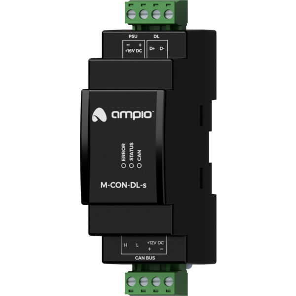
The image above is for illustration purpose only. The actual module may vary from the one presented here.
There are two methods for connecting the power supply to the M-CON-DL-s module, depending on the number of controllers. A detailed diagram is provided at the end of this manual.
Module M-CON-DL-s is a component of the Ampio system. Required voltage to power the module is 11 — 16V DC. The module is controlled via CAN bus.
The module is intended for integration with lighting with a Dali interface. Dali is the main lighting used in industrial halls, large-format supermarkets and with the ongoing rapid development of automation systems, also in residential buildings.
The module allows one to control up to up to 64 lights lamps. Each lamp can be controlled independently.
Both buses used by the device are galvanically isolated from each other.
For proper functioning, the Dali bus requires a specialised power supply to be connected to it. The M-CON-DL-s module can act as such a power supply for the attached Dali bus segment.
As part of the Dali standard, the typical value of the current efficiency of a specialised power supply is defined as 250mA. It should be borne in mind that the current efficiency of the M-CON-DL-s built-in power supply is 100mA. For most Dali bus devices, the bus controllers are powered by power supplies built into the devices, while the bus current load implied by each device is minimal. However, there are devices that are fully bus-powered. If one wants to use such devices, one must verify that the efficiency of the built-in power supply is sufficient.
To use the specialised Dali power supply built into the module, an additional 15 — 20V DC power source must be attached to the module.
The module is designed for mounting on a 35mm DIN rail. The module’s width is 35mm, 2 spaces/modules in DB. In order to start the module, it must be connected to the CAN bus. The bus of the Ampio system consists of four wires - two for power and two for communication between the modules.
In addition to the CAN bus connector, the device has a connector that provides two communication lines constituting the Dali bus (D + and D-) and a connector for an additional power source necessary if one wants to use the built-in specialised Dali bus power supply.
On the front of the module there are signalling LED indicators. The green LED with the label CAN indicates the status of communication on the CAN bus:
Apart from the LED indicating the communication bus status, there are two red LEDs on the front of the device:
The module is programmed with the use of the Ampio Designer software. It allows you to modify the parameters of the module and define its behaviour in response to signals directly available to the module as well as general information coming from all devices present in the home automation bus.
When using the M-CON-DL-s module with the Ampio SmartHome Configurator tool, the module’s firmware must be lower than 11600. For the Ampio Designer tool, firmware higher than 11600 is required.
Dimensions expressed in millimeters.
 Click to enlarge and open in a new tab.
The wiring diagram shown on the left is suitable for smaller systems with a small number of controllers. Above 20 Dali controllers, use the diagram with the dedicated power supply shown on the right.
