The image above is for illustration purpose only. The actual module may vary from the one presented here.
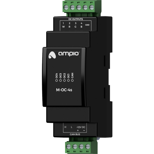
Module M-OC-4s is a component of the Ampio system. Required voltage to power the module is 11 — 16V DC. The module is controlled via CAN bus.
The module has four OC outputs and supports the functionality of an RGBW lighting controller.
The module has open-collector outputs allowing for smooth control of resistive loads supplied with voltage of up to 40V DC. It is also allowed to control loads of moderate inductive nature, in particular relays. Control is performed by the method of pulse-width modulation (PWM). Internally, each of the outputs allows the connected line to be short-circuited to the module’s ground.
As part of the module’s configuration, it is possible to activate the functionality of the RGBW lighting controller. Nominally, each of the open-collector outputs is controlled independently. When the functionality is activated, the control is done by defining the colour and intensity of the light.
The module is designed for mounting on a 35mm DIN rail. The module’s width is 35mm, 2 spaces/modules in DB. In order to start the module, it must be connected to the CAN bus. The bus of the Ampio system consists of four wires - two for power and two for communication between the modules.
In addition to the CAN bus connector, the device has a connector that allows for the connection of four resistive loads to open-collector outputs.
When using the open-collector outputs functionality, it should be borne in mind that the supply circuits of the connected loads are closed by the mass of the module. Therefore, it should be ensured that the mass of the device is connected to the mass of the power supply with a cable of appropriate thickness.
On the front of the module there are signalling LED indicators. The green LED with the label CAN indicates the status of communication on the CAN bus:
Apart from the diode that indicates the status of the communication bus, on the front of the device there are also four red diodes indicating the status of the open-collector outputs.
The module is programmed with the use of the Ampio Designer software. It allows you to modify the parameters of the module and define its behaviour in response to signals directly available to the module as well as general information coming from all devices present in the home automation bus.
Dimensions expressed in millimeters.
 Click to enlarge and open in a new tab.
The presented power supply of OC outputs controlled devices is for reference only. The module can control loads with a supply voltage up to 40V DC.
