M-CON-KNX-s: KNX integration module MKNX-1s

  • Document number: PO-036-EN
  • Version: 1.0.0
  • Date of publication: February 23, 2022


The image above is for illustration purpose only. The actual module may vary from the one presented here.

Technical data

Supply voltage
11 — 16V DC
Current consumption
15mA
Communication interface
KNX
Current consumption from the KNX bus
5mA

Dimensions

Width
35mm, 2 spaces/modules in DB
Height (incl. plugs)
110mm
Depth
59mm

Environment

Temperature
-40 — 50°C
Humidity
≤95%RH, non-condensing

General features

Module M-CON-KNX-s is a component of the Ampio system. Required voltage to power the module is 11 — 16V DC. The module is controlled via CAN bus.

The module enables two-way communication between devices operating within the CAN and KNX bus. Both buses used by the device are galvanically isolated from each other.

M-CON-KNX-s module is unavailable until further notice.

Installation

The module is designed for mounting on a 35mm DIN rail. The module’s width is 35mm, 2 spaces/modules in DB. In order to start the module, it must be connected to the CAN bus. The bus of the Ampio system consists of four wires - two for power and two for communication between the modules.

In addition to the CAN bus interface, the device has a two-wire KNX bus interface.

Device status LEDs

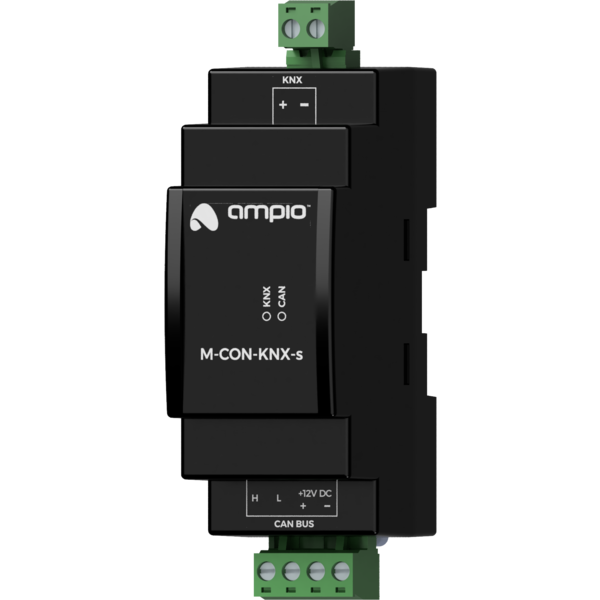
On the front of the module there are signalling LED indicators. The green LED with the label CAN indicates the status of communication on the CAN bus:

  • one regular flash every 1 sec. – CAN bus communication is working properly,
  • two regular flashes every 1 sec. – the module is not receiving information from other modules,
  • three regular flashes every 1 sec. – the module cannot send information to the CAN bus;

In addition to the LED indicating the status of the CAN bus, on the front of the device there is also a red LED labelled KNX. If it lights up, it means that the devices have received a KNX telegram.

Programming

The module is programmed with a special programmer, available for authorised technicians, and the Ampio Smart Home CAN configurator software. It allows you to modify the parameters of the module and define its behaviour in response to signals directly available to the module as well as general information coming from all devices present in the home automation bus.

Defining the behaviour of the device in the context of the main functionality of the module - the communication gateway between the two standards of the building automation buses - should be considered separately for each communication direction. In both cases, this configuration boils down to defining a list of translation rules between protocols.

All the operations described in the following subsections are performed using the Smart Home CAN configurator software.

CAN to KNX translation

When preparing the rules for translation from the CAN bus to KNX, a KNX individual address should be assigned to the M-CON-KNX-s device. Each telegram transmitted by the device on the KNX bus will have this address in the source field.

The next step is to define a list of translation rules. Each translation rule points to a single output value of a specific device running on the CAN network. Sending of a telegram to the KNX bus is triggered by changes to its value. The form of the telegram to be sent is defined by specifying the destination group address (unicast messages are not supported), as well as the value of the control field and the KNX telegram command. The last component of the translation rule is a definition of the KNX data type on which the value from the device operating in the CAN network is to be cast.

KNX to CAN translation

Each translation rule from the KNX bus to CAN defines the destination group address of the expected telegram (receiving unicast messages is not supported) and the data type of its content. During translation, the value of the telegram command field is not interpreted. After receiving a telegram directed to a defined group address, the M-CON-KNX-s module interprets its content in accordance with the indicated data type and sends a message to the CAN network. The form of the sent CAN frame is defined by specifying the source MAC address of the virtual device on behalf of which it will be sent, and the data type on which the value from the device operating within the KNX bus will be cast.

Module dimensions

Dimensions expressed in millimeters.

Click to enlarge and open in a new tab.

Connection diagram

Click to enlarge and open in a new tab.