M-OC and M-INOC modules are equipped with open-collector type inputs, which enable the modules to control resistive loads supplied with voltage up to 40V DC. M-INOC type modules are additionally equipped with ground-detecting inputs.
The M-INOC-8s module is a component of the Ampio system and can be used for:
The device’s eight outputs are capable of independently controlling eight receivers. The OUT1 to OUT8 outputs initiate the ground impulse and ar also equipped with pulse-width modulation (PWM), thanks to which they enable, for example, LED diodes' brightness adjustment.
This document is meant to explain the configuration of the M-OC and M-INOC type of modules, using the specific example of M-INOC-8s.
To change the device parameters, enter the device settings ( cog icon) and select the Parameters tab on the left. In the Curve Values sub-tab, it is possible to set the control for each channel separately.
 Click to enlarge and open in a new tab.
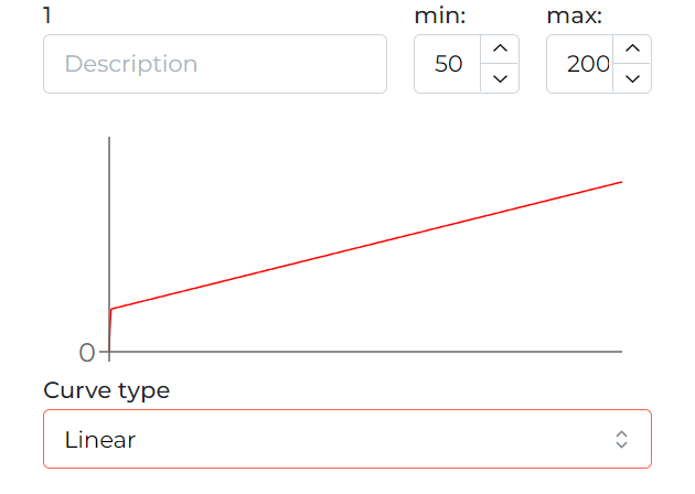
The output can be controlled in a linear characteristic in several different ways. Moreover, the start and end of the control do not have to mean 0 and 100% either (select any value from the range 0-255). After the change has been made, send the new parameters to the device.
 Click to enlarge and open in a new tab.
The current values can be viewed and set in the Functions tab, OC sub-tab.
 Click to enlarge and open in a new tab.
Logical conditions can be created both from output values and to control outputs. Detailed function parameters are set by clicking on the cog icon on the dark background.
 Click to enlarge and open in a new tab.
*from January 2024, the Smart Home Configurator software is no longer being developed. It is recommended to use it only in substantiated instances.
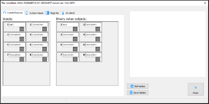
M-INOC-8s is configured in the Ampio Smart Home configurator application. In order to check if the module is working correctly, open the Device monitor. There, you can also activate the outputs and inputs, and name them. To save your changes, click Save names.
 Click to enlarge and open in a new tab.
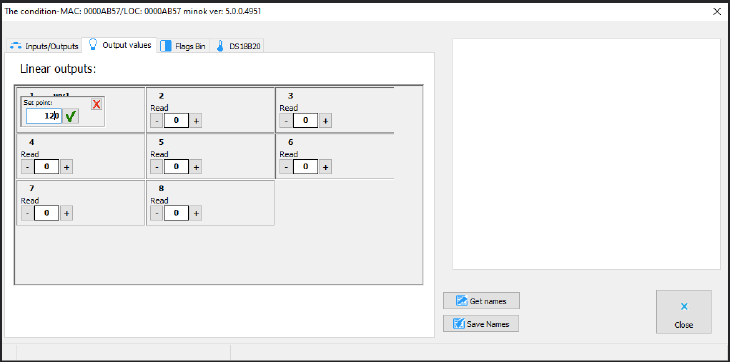
Apart from the simple on/off information, in the Output values tab you can also define a value per output within the range of 0-255.
 Click to enlarge and open in a new tab.
Flags in this module work in exactly the same fashion as it is the case with all the other Ampio system modules. The Device monitor allows you to also search for and name the DS18B20 temperature sensors.
In the Device parameters window, you can change the frequency of the PWM outputs' modulation.
 Click to enlarge and open in a new tab.
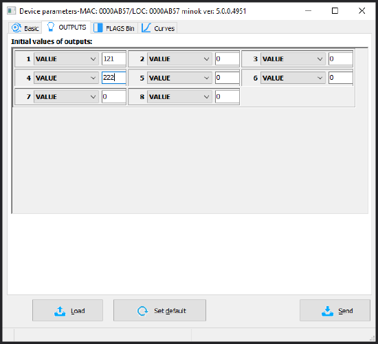
In the OUTPUTS tab, you can define the value to which selected outputs will be set after a power reboot. Initial values can also be set up for particular flags after selecting the right tab (FLAGS Bin).
 Click to enlarge and open in a new tab.
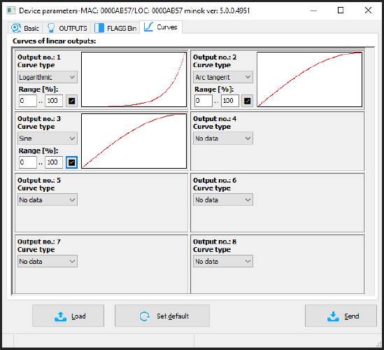
The Curves tab provides options for specifying how an output should be activated. Select the control range - for some devices a range between, e.g. 20% and 80% is advantageous. Then, select one curve from the list - this will create a better visual effect when switching the lights on. Available curves are: line, logarithmic, sine, tangent, and arc tangent. After confirming, you will see a graph corresponding to the setting. Once this stage of configuration is completed, click on send to device.
 Click to enlarge and open in a new tab.
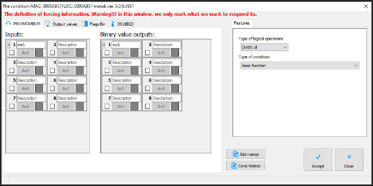
When creating conditions in Smart Home configuration, you can establish dependencies from the M-INOC module or control it. Dependencies can be created from the input, output, flag, or the temperature sensor. If you want to check whether an output is switched on, or not, tick the appropriate output in the Inputs/Outputs tab (Binary value outputs).
 Click to enlarge and open in a new tab.
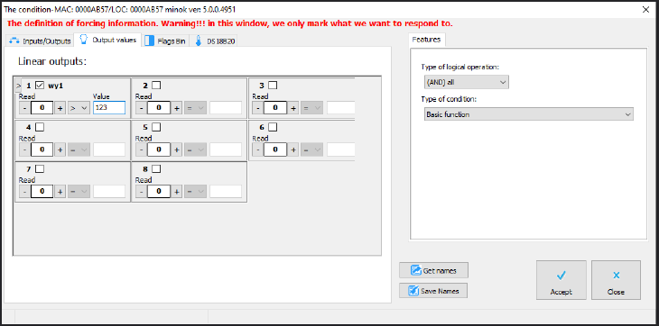
If you would like to ascertain whether the selected output has reached its set value (e.g. 100), you can do that in the Output values tab.
 Click to enlarge and open in a new tab.
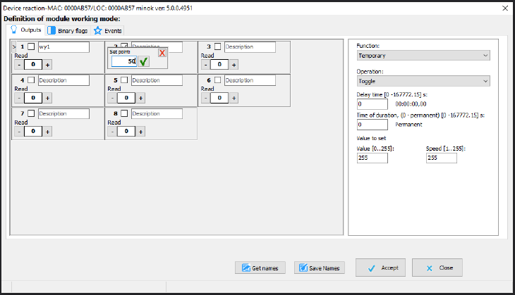
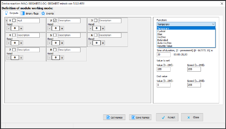
As a reaction to any condition, you can select one of various functions that can be controlled by M-INOC-8s' outputs. In the figure below, on the left side, there is an overview of current values, which can be edited to test the reaction of a given output.
 Click to enlarge and open in a new tab.
On the right side, you can select what function should be used in the condition and set its parameters. For example, for the Temporary function of the Switch off/Set as temporary operation, define the delay, duration (0 means permanent), value to set, change pace and, optionally, end value (if duration is different from 0), as well as the speed of reaching the end value.
 Click to enlarge and open in a new tab.
Once the condition is created, it is necessary to confirm it and send it to device.