In this document, a software solution for integration devices is presented. It is a software solution for integration with most devices supporting MODBUS RS485 protocol. It has the ability to communicate bidirectionally with devices connected to the RS485 bus.
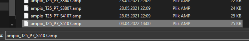
In order for the M-CON-485-s device to have the described functionality, it must be loaded with software with a 7 suffix, such as a file named: ampio_T25_P7_S6407.amp. Due to the different types of functions that MCON family devices perform, updates to their software may not be signaled like the others. They have to be uploaded manually by selecting the software version in the SOFT column by choosing the appropriate file from the drive or software number.
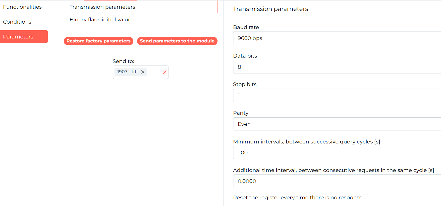
After selecting the M-CON-485-s device in the list and entering its parameters (cog icon), there are 3 main tabs on the left side of the screen. To change the transmission settings, select Parameters and then Transmission Parameters.
 Click to enlarge and open in a new tab.
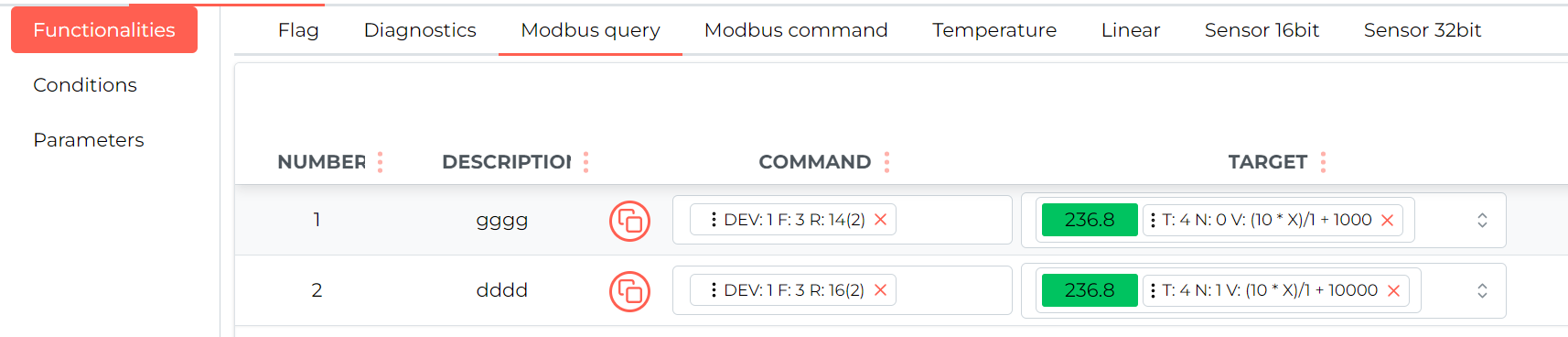
Queries are created in the Functions tab, in the Modbus - Queries sub-tab.
 Click to enlarge and open in a new tab.
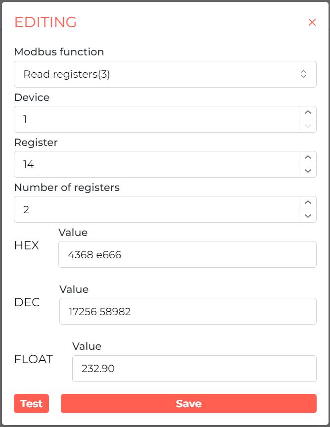
By editing the contents of the command column, you can select the Modbus function, the device ID, the Register to which you are sending the query, and the number of registers (some data is written to more than 1 register in order). Clicking the Test button gives a preview of the current values from the register.
 Click to enlarge and open in a new tab.
The next column CEL sets the form in which the register result is to be presented to the Ampio system. If more than 1 register is queried at a time, and the value starts not in the first of them, the data reading offset can be set. Next, the data type in Modbus is selected, then the data type to be sent in Ampio and the value number. If the value is still to be multiplied, divided or shifted (e.g., adding a value of 100 to the result), expand VALUE MODIFICATION and enter the multiplier, divider or offset. After making changes, select Save. After editing the target, the current value can be seen in the green box.
 Click to enlarge and open in a new tab.
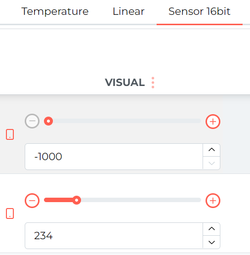
The values sent on the Ampio bus can then be previewed in the corresponding sub-tab, e.g. Sensor 16bit.
 Click to enlarge and open in a new tab.
The 32-bit values in Ampio system are for data viewing, you can’t make logical conditions from them.
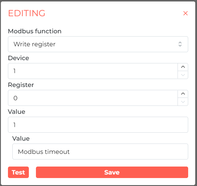
To send a command to the Modbus, select the Modbus - commands tab, add a new command via the + button in the upper right corner, and then edit the contents of the COMMAND tab. Here you can change the query function, the device ID, the register to which the data is sent and the value sent. The return value, if any, will appear in the Value field.
 Click to enlarge and open in a new tab.
*from January 2024, the Smart Home Configurator software is no longer being developed. It is recommended to use it only in substantiated instances.
Available from the Ampio Smart Home configurator version 5.0.0.2359
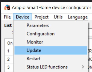
In order for the M-CON-485-s to support the described functionality, it has to have software ending in ‘7’ installed, for example a file called: ampio_T25_P3_S707.amp. Due to different types of functions that the M-CON family devices perform, their software updates are not automatically signalled, as it is the case with other modules. You have to install the updates manually by going to Device>Update and selecting the right file.
 Click to enlarge and open in a new tab.
 Click to enlarge and open in a new tab.
To configure parameters of a device, you will need its MODBUS protocol documentation, i.e. a list of registers that specifies the value and download method.
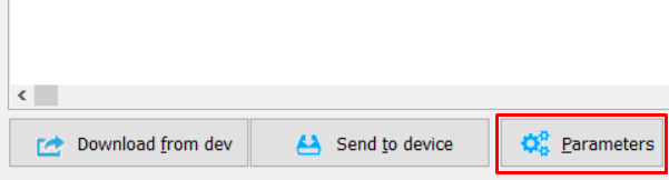
Parameters are available in the parameters tab of the MODBUS device, which can be opened by clicking on the Parameters button shown below, accessible in the device configuration in the device configuration window.
 Click to enlarge and open in a new tab.
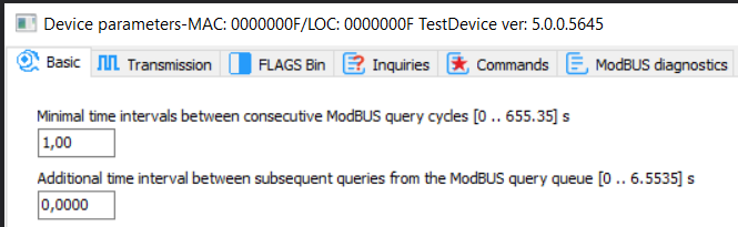
In the Basic tab, you can decide whether the device’s flags will be visible to other devices in the Ampio network, or not.
 Click to enlarge and open in a new tab.
The Minimal time intervals … parameter defines the minimal intervals between consecutive broadcast gateways in the Ampio network with information received from the RS485 bus. The value is provided in seconds with accuracy of 0.01s. The value must be between 0.01s and 655.35s (the maximum interval being 10min 55.35s). By default, it is set to 1s. The other parameter defines the intervals between consecutive queries (creating queries will be explained further in this document).
Transmission parameters tab.
All MODBUS devices must have identical RS485 port transmission parameters set. This can be achieved by using the Ampio CAN configurator and setting the same parameters in your device.
 Click to enlarge and open in a new tab.
In this tab, you can set the transmission speed. All standard speed values are available - from 300 to 230400 bps.
Here is the full list of available speed values: 300bps, 600bps, 1200bps, 2400bps, 4800bps, 9600bps, 14400bps, 19200bps, 28800bps, 38400bps, 57600bps, 76800bps, 115200bps, 230400bps.
The most commonly used default speed in devices is 9600bps. Naturally, the majority of devices allow you to change each of the transmission parameters so that they can be adjusted to the length of the bus cable and conditions under which they operate. This is where you change all parameters to match the devices connected to the RS485 bus.
Binary and line flags work in exactly the same way as they do in all the other Ampio modules.
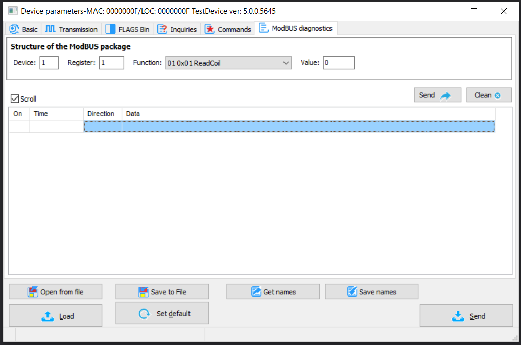
A useful tool when doing the configuration is the MODBUS function tester. It gives you the possibility to send data to a device and preview the device’s response. Thanks to the tester, you can verify the data available in the manufacturer’s specification and analyse the device’s responses in order to later use them when defining queries and commands.
The monitor is available in the ModBUS diagnostics tab shown below.
 Click to enlarge and open in a new tab.
What you will find here are: gateways broadcast to the device, Send button, a response table and Clear button, which deletes the whole list.
Description of fields:
All values are provided in decimals.
 Click to enlarge and open in a new tab.
When using the multiple values write function, for example function 15 or 16, subsequent values are separated by a comma, as shown in the figure above.
After filling all fields in as intended, press Send.
The list will get a new row with four columns. The first column is an item number. The second one displays the time that passed between switching on the computer and an event happening. The third column shows the direction of communication. The last column provides feedback or returns an error message.
The figure below shows feedback (error - timeout) to a submitted function, to which the module did not respond.
The feedback message will indicate, where an error occurred.
 Click to enlarge and open in a new tab.
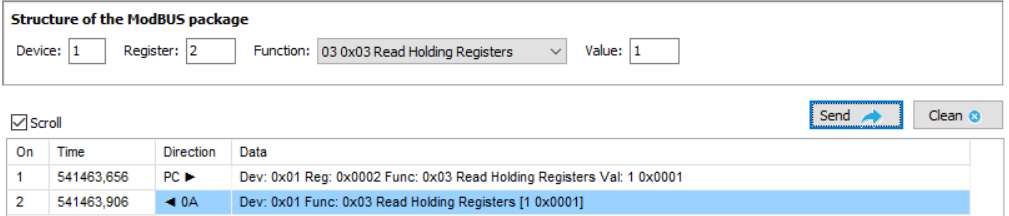
An answer to a correct query about the register no. 2 is shown below. The M-CON device with address 9C14 responded with the register value 1.
 Click to enlarge and open in a new tab.
The data is shown in decimal and hexadecimal form.
Testing function is very useful both, when checking the defined queries, and commands. Apart from its basic purpose, it also provides the option to set the device parameters during the first device launch. The function can also be helpful for reading values, e.g. error statuses during diagnostics, when the values do not matter for everyday operations and there is no need to retrieve them permanently for the Ampio system.
In the Inquiries tab, define a list of queries for the device and interpretation of the device’s response to the queries.
You will need MODBUS protocol documentation for the queried device.
In this document, an example of receiving information from the F&F LE-03MW CT electricity meter is presented.
Below, you will see the tab for defining queries that shows an empty list before the first query is stipulated.
 Click to enlarge and open in a new tab.
In the newest version of the configurator, it is also possible to detect collisions of queries. if the Data target type and Data target number are already used, the captions will be highlighted in red.
 Click to enlarge and open in a new tab.
Add a new query by clicking on the Query button with a plus sign. Fields for editing the query will show up on the right side.
 Click to enlarge and open in a new tab.
The description of the query is displayed in the query tree and makes recognising the construction later easier.
In the Device address field, enter the device’s address number from the MODBUS bus, in accordance with its configuration. In this document, a sample address number 1 was used.
In the case of the meter used for the purpose of this documentation, registers should be read with the use of the function no. 3 chosen from the Function list. Let’s assume that there is only one unit connected with the ID=1 and you want to get the duration of displaying the view from it. Following the documentation, enter 13 in the Register field. After completing all the fields, confirm the provided information by clicking Confirm.
Below is a screenshot of the registers' description from an F&F documentation.
 Click to enlarge and open in a new tab.
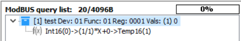
After this operation is completed, the defined query will show on the list, as shown below.
 Click to enlarge and open in a new tab.
In the square brackets, there is information about the number of processing functions (in this example, there are none, but it will be explained further in the document, how to create them and what they are used for). If a query had a description, it will be displayed together with the queried device’s address, which is shown in positions 1-3. If, however, the description has not been provided, the full query structure will be displayed, i.e. the device’s address, the Modbus function number, register address and the data length - all visible in the last position on the list.
However, for the value retrieved by the query to be available in the Ampio system, analysis of the received data must be conveyed. This is what the processing functions are used for.
The figure below shows that the description of the added row reflects the values that were supplied.
 Click to enlarge and open in a new tab.
For each of the queries, up to 10 such functions can be defined. In our example, returned responses have single values, so each of the queries requires only one processing function.
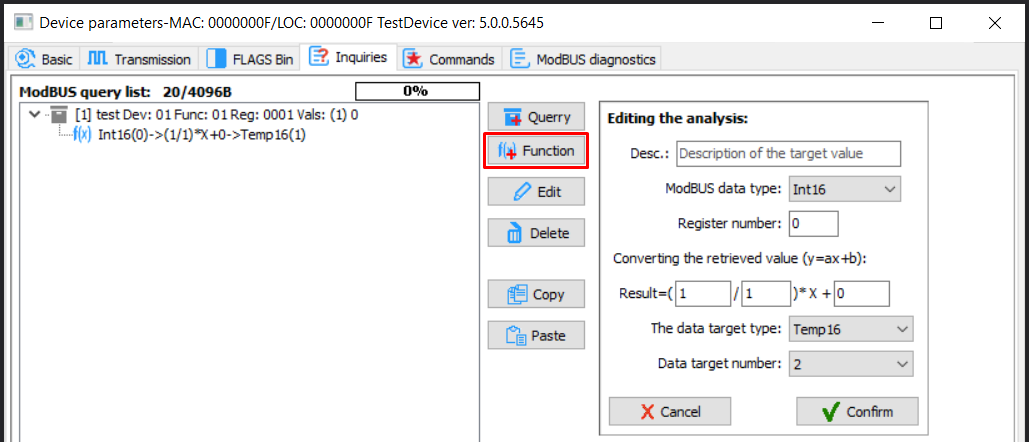
As soon as you have selected a query, click on Function. You will see fields appear, in which you can define the data analysis functions.
 Click to enlarge and open in a new tab.
The ModBUS data type field is a type of data that is analysed in a response to a query. The available types of data are as follows:
The next field Response byte defines the number of response package.
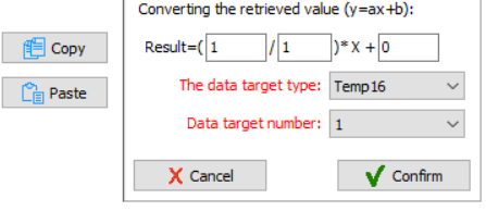
Other fields are used to define the value converter according to a simple line corelation:
Now, it is time to decide, how the data will be delivered to the Ampio network. In the Data target type field select the data information type according to the Ampio broadcast standard. You can choose between:
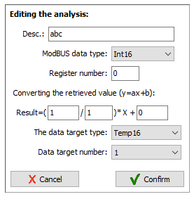
In the Target data number enter the value index for a given type. In the Ampio system, the number of particular values is also defined - each device can send a couple/dozen specific types of data, numbered from 1 up, e.g.:
NB!
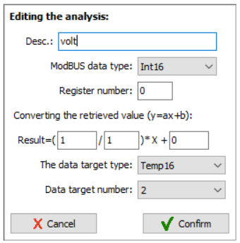
The differences in sending data types between different networks must be borne in mind. For example, when calculating temperatures:
Let’s assume that temperature values are sent from the ModBUS network with 0.1⁰C accuracy as signed integer multiplied by 10. It means that value 1 equals 0.1⁰C. It is identical in the Ampio system. However, in case of temperatures in Ampio, values are sent as UInt16, which is an unsigned integer. To enable sending a negative number, an offset equal to 1000 has been applied.
Therefore, 1000 must be added to the value received from a device (e.g. a recuperator). Implementation of this rule is shown below.
 Click to enlarge and open in a new tab.
A list of commands is used to control devices, e.g. to set the rotational speed of recuperator’s fans from the touch panel. mobile app, or as a reaction to household members' presence.
This document will present an example of configuration for a ZEFIR recuperator.
Commands will be created to control the efficiency of air supply and extraction.
Similarly to queries, commands are also divided into blocks. That makes it possible to send multiple commands with one function triggered. Some recuperators or other devices, in order to reach certain parameters, require setting up a couple of register values, e.g. in case of ventilation efficiency, sometimes it is needed to set air supply and extraction separately, or define some additional parameters. Here, air supply and extraction will both be set up using one function.
The commands tab looks similar to the one for downloading values.
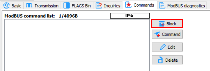 Click to enlarge and open in a new tab.
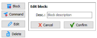
Command blocks are added by clicking on the Block button shown above.
Once you click it, you will get an option to enter the name of the block. Providing the name will make it much easier to use the block’s definition during the configuration of its functions and any future changes.
 Click to enlarge and open in a new tab.
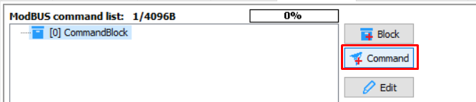
After confirming, you will notice a new entry on the list of command definitions. Here, similarly to the previous example, you will stipulate constituent commands in the block by clicking on Add command.
 Click to enlarge and open in a new tab.
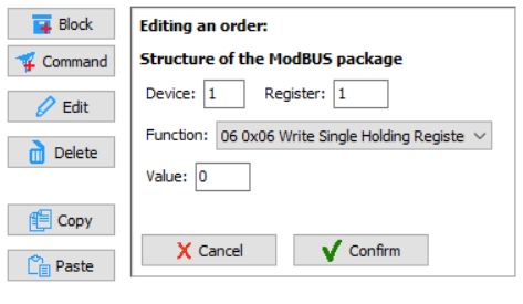
Then, command definition fields will show, as presented below.
 Click to enlarge and open in a new tab.
Here, you can see all command elements that have to be completed. You will have to use the ZEFIR recuperator’s documentation again in order to do that.
According to the ModBUS standard, there are a couple of functions that enable saving data in devices.
The application supports the following instructions 05, 06, 15, 16. Each of them has a different meaning and usually, the choice of the instruction is indicated in the documentation of an integrated device.
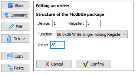
As described above, in order to set a value, you will use the MODBUS function number 6 (Write Single Register). Again, let’s assume that the device address equals 0. In the documentation, look for the correct register and value to set up the air supply.
2.4. Air supply efficiency Register address (offset): 0003 Mode: read/write In case of a handling unit with a STANDARD driver, the register contains data about the number of activated gear in the air supply fan; other drivers provide a percentage value. The air supply efficiency may be controlled by sending the correct value to the register. Sent/received data: 1 – 5: gear number for a STANDARD driver 20 – 100: efficiency percentage for other drivers
Let’s assume that you have a driver with smooth air supply and extraction regulation from 20 to 100%.
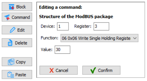
As presented, in order to set the fan to 30%, you must enter 30 in the register number 3. Then, complete the other fields, as shown below.
 Click to enlarge and open in a new tab.
Click on Confirm to save the changes. You will then see the first element of the block.
 Click to enlarge and open in a new tab.
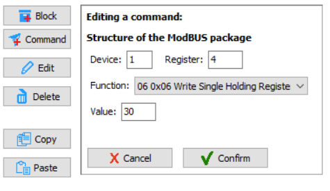
Now, let’s add a command that will set the efficiency of air extraction to 30%, similarly to the example of air supply and in accordance with documentation.
 Click to enlarge and open in a new tab.
2.5. Extraction efficiency Register address (offset): 0004 Mode: read/write In case of a handling unit with a STANDARD driver, the register contains data about the number of activated gear in the air extraction fan; other drivers provide a percentage value. The air extraction efficiency may be controlled by sending the correct value to the register. Sent/received data: 1 – 5: gear number for a STANDARD driver 20 – 100: efficiency percentage for other drivers
In the block, add another command and fill the appropriate fields in, as shown below.
 Click to enlarge and open in a new tab.
After confirming, you will get the sample set of commands shown in the figure below.
 Click to enlarge and open in a new tab.
Similarly to the steps described above, create other blocks - the ones responsible for ventilation efficiency, or other device parameters.
Changing the block’s name, or specific commands, same as with queries about values, can be done by clicking on the Edit button.
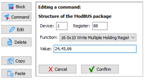
If there is a necessity of using the save option for multiple registers with the 15 (Write Multiple Coils) or 16 (Write Multiple Holding Registers)function, the configuration looks similar. The only difference is the method of entering the values to be sent. In the value field, enter consecutive numbers in decimal format, divided by commas. A sample command configuration with the use of function 16 is presented in the figure below.
 Click to enlarge and open in a new tab.
Such formulated command blocks can now be used in the Ampio system functions.
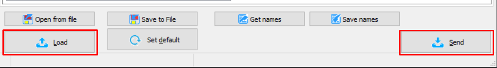
Identically to other devices, a prepared parameters configuration should be sent to the device. This operation can be performed by clicking Send.
 Click to enlarge and open in a new tab.
Receiving parameters happens automatically when opening the configuration window. If, however, a need arises to download them again, it can be done by clicking on Load shown above.
There is an option to store parameter data in a file. The file can be moved and uploaded multiple times. This makes it possible to create backups of setting, ready-made configuration sets to use in the future, or a database of configurations that can be shared with other installers for the integration of various devices.
The file stores all device’s parameter values, including the descriptions of command blocks and query functions. The file does not include other values, so that the data that is not editable in this window do not get overwritten, e.g. flag names when importing ready-made ModBus configuration parameters.
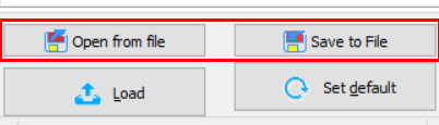
Saving and reading data from a file is done by clicking either the Open from file or Save to file buttons shown below.
 Click to enlarge and open in a new tab.
The default location of configuration backup files is the following folder:
Disk:\Users\{USER}\Ampio\AmpioSmartHome\Params\
The default file name consists of the following Param-{MAC}-{TIME}.ashparxml
It is an XML file, which contains binary forms of parameter elements.
For the sample configuration here, let’s use our module with a touch panel. Command blocks that will set the air supply efficiency of the recuperator to 3 different speeds have been set up.
 Click to enlarge and open in a new tab.
Dedicate one touch field of the used M-DOT device to the execution of each block.
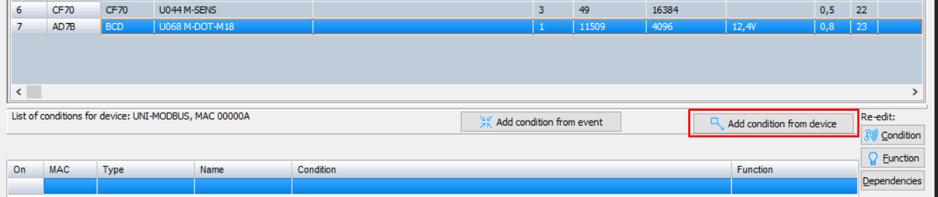
In the U025 MCON485 device’s configuration window select the touch panel and add a new condition from the panel.
 Click to enlarge and open in a new tab.
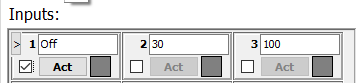
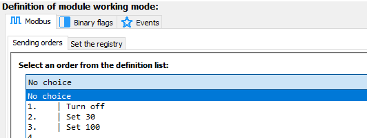
The first field should switch the ventilation off, the second one should set it to 30%, and the third one to 100%.
As per usual, create a basic condition from the filed no. 1 and confirm, as shown below.
 Click to enlarge and open in a new tab.
You will see a function construction window, where you must go to the MODBUS function tab and select the right function, defined earlier in the parameters, from a drop-down list. In the field no.1 it will be the Turn off function.
 Click to enlarge and open in a new tab.
The usefulness of command blocks' descriptions in parameters is visible here. Without them, there would only be function numbers shown. The functions will, naturally, still work, but configuration of the system without some notes on a piece of paper would be very tricky.
Confirm in order to get a field that will switch off the ventilation. Its description is also shown on the list of conditions.
 Click to enlarge and open in a new tab.
Create more conditions in the same way as described above. For field no. 2 set the ventilation to 30%, and for field no. 3 to 100%. Send the list of created conditions to the device.
Thanks to creating the queries function and selecting where the selected data should go to, the information is sent to the bus. Apart from them being shown in applications on a smartphone, or a tablet, they can also be used to create a condition.
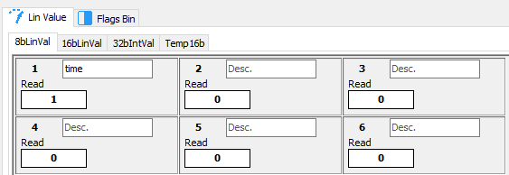
The tab for configuring conditions from 8-bit values is presented in the figure below.
 Click to enlarge and open in a new tab.
There is a possibility of entering 8-bit data in 18 places. As a result, they are sent to the bus in 3 separate broadcast-type messages (6 pieces of data per 1 broadcast). This allows you to use 6 neighbouring values (1-6 or 7-12 or 13-18) in the construction of one condition.
 Click to enlarge and open in a new tab.
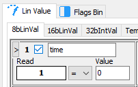
The figure above presents a basic construction component, which means a single 8-bit value. It shows also the value’s number, selection field, its description, the current reading and condition value.
In these conditions, you can check whether the value is equal (=), bigger than (>), smaller than(<), or different from (!=) the provided value.
| DEC | HEX | Function description |
|---|---|---|
| 1 | 0x01 | Read Coils - Read the state of binary outputs, relay outputs |
| 2 | 0x02 | Read Discrete Inputs - Read the state of binary inputs, e.g. case closing switches |
| 3 | 0x03 | Read Holding Register |
| 4 | 0x04 | Read Input Register - Read the analogue output, e.g. temperature sensor values |
| 5 | 0x05 | Write Single Coils - Write a single binary input, e.g. controlling a relay |
| 6 | 0x06 | Write Single Holding Register |
| 15 | 0x0F | Write Multiple Coils - Write multiple binary outputs, e.g. intended control of a couple of relays |
| 16 | 0x10 | Write Multiple Registers - e.g. write into registers of data longer than 16 bits |