The image above is for illustration purpose only. The actual module may vary from the one presented here.
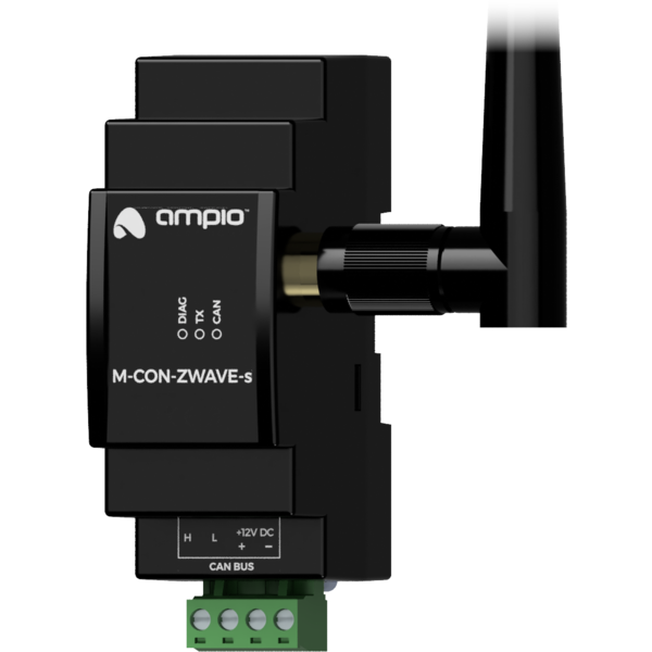
Module M-CON-ZWAVE-s is a component of the Ampio system. Required voltage to power the module is 11 — 16V DC. The module is controlled via CAN bus.
The module allows for integration with a number of devices that support the Z-Wave wireless communication protocol.
The following list includes Z-Wave devices that can be integrated with the M-CON-ZWAVE-s module.
The module is designed for mounting on a 35mm DIN rail. The module’s width is 35mm, 2 spaces/modules in DB. In order to start the module, it must be connected to the CAN bus. The bus of the Ampio system consists of four wires - two for power and two for communication between the modules.
In addition to the CAN bus connector, the device has an SMA connector for a Z-Wave antenna. The connector is on the right side of the module, therefore it is recommended that the module is installed on the right side of the distribution board, so that it is possible to attach an antenna or an antenna’s cable to it.
On the front of the module there are signalling LED indicators. The green LED with the label CAN indicates the status of communication on the CAN bus:
Apart from the communication bus status LED, there are two red LEDs on the front of the device:
The module is programmed with a special programmer, available for authorised technicians, and the Ampio Smart Home CAN configurator software. It allows you to modify the parameters of the module and define its behaviour in response to signals directly available to the module as well as general information coming from all devices present in the home automation bus.
Pairing of supported device with the M-CON-ZWAVE-s module is initiated from the Smart Home CAN configurator application. After putting the device into pairing mode, follow the pairing procedure defined by the manufacturer of the paired device.
Once pairing is completed, the connected device will be seen by the building automation system as a virtual device.
It is not recommended to use more than 8 slave modules per one base station module. Installing more modules may result in excessive load on the wireless network and improper functioning of the system.
Dimensions expressed in millimeters.
 Click to enlarge and open in a new tab.
