The image above is for illustration purpose only. The actual module may vary from the one presented here.
Module WL-OC-RGBW1p is a component of the Ampio system. Required voltage to power the module is 11 — 16V DC. The module is controlled via the Ampio LoRa wireless interface.
The module has four OC outputs operating in an RGBW lighting controller mode.
WL-OC-RGBW1p outputs can only be operated in an RGBW lighting controller mode. It is not possible to switch them over to an independent control mode.
The module has open-collector outputs allowing for smooth control of LED RGBW lighting supplied with voltage of up to 40V DC. Control is performed by the method of pulse-width modulation (PWM). Internally, each of the outputs allows the connected line to be short-circuited to the module’s ground.
The dimensions of the module enable its installation in a standard junction box. In order to start it up, it must be connected to the power supply and paired with the module acting as an Ampio LoRa base station in the wired segment of the building automation installation.
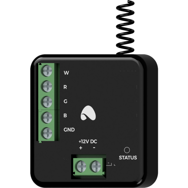
The module has two connectors with screw terminals. They enable the connection of power lines of various devices and connection of RGBW LED lighting’s channels of individual colors.
The WL-OC-RGBW1p module allows one to control lighting powered with voltage up to 40V, however, it itself requires voltage in the range of 11 — 16V DC.
If the supply voltage of the controlled light source is not in the range of 11 — 16V DC, it is necessary to provide two power lines - one for the light source and one for the module.
On the front of the module there are signalling LED diodes. The green LED with the label STATUS indicates the status of communication on the Ampio LoRa interface.
The programming of the module is executed using the Ampio Designer tool. It allows modifying the module’s parameters and defining its behaviour in response to signals directly available to the module. It also provides access to all the information coming from all the devices present within the building automation bus.
Before starting configuration activities, it is necessary to pair the device with the module acting as the Ampio LoRa base station in the wired part of the building automation installation. To do this, using the Ampio Designer software, put the base station module into search mode for modules from the WL group. While the search mode is active, press the pairing button three times on the activated radio module. If the operation is successful, the found device will appear in the list of paired wireless modules in the Ampio Designer software.
It is not recommended to use more than 8 Ampio LoRa wireless modules per one base station module. Installing more modules may result in excessive load on the wireless network and improper functioning of the system.
Programming the rules for which the WL-OC-RGBW1p module is to be an executive device, is defined during the configuration of the base station module. In order to create rules whose triggering depends on the state of the WL-OC-RGBW1p module, it is necessary to add it to the device list as a virtual device.
Dimensions expressed in millimeters.
The dashed lines mark the areas where the device connectors or its other elements can be located.
 Click to enlarge and open in a new tab.
