The image above is for illustration purpose only. The actual module may vary from the one presented here.
Module WL-REL-ROL1p is a component of the Ampio system. Required voltage to power the module is 110 — 250V AC. The module is controlled via the Ampio LoRa wireless interface.
The module has two AC inputs and two relay outputs in the roller shutter and blinds' drive controller mode.
WL-REL-ROL1p outputs can only be operated in roller shutter and blinds drives' controller mode. It is not possible to switch them over to an independent control mode.
The module has relay outputs that enable switching on resistive and inductive loads. The module relays are normally open. The table below shows the permissible operating parameters of the relays depending on the nature of the load.
| The nature of the load | Maximum long-term permissible current |
|---|---|
| AC1: Resistive or moderately inductive AC loads | 10A |
| AC15: Inductive AC loads | 1.5A |
One of the contacts of each of the relays is connected to the power phase of the module.
Relay outputs of the device work as a single compound output dedicated to controlling devices powered by electric motors with a variable direction of movement, and a limited movement range. For example, roller shutters and blinds drives. This mode can also be used in the case of other devices of a similar nature, such as e.g. gates.
Roller shutters and blinds' drive controller is designed to control devices with built-in limit switches that disconnect the drive’s power supply when the ends of the range of motion are reached.
The control of a pair of relays operating in the roller shutters and blinds' drive controller mode is performed by closing and opening commands, or by setting the opening level. When it comes to blinds, it is also possible to set the position of slats.
During operation, the module estimates the state of the controlled device, i.e. the degree of opening and the position of slats (if applicable). This information is available within the building automation bus and is used internally to perform control in terms of the degree of opening, or deflection angle of the slats.
A single pair of relays operating in a controller mode for roller shutters and blinds' drives can only be connected to a single drive. Any other connection may result in incorrect operation of the device, as well as permanent damage to both, the module and the drive.
The dimensions of the module enable its installation in a standard junction box. In order to start it up, it must be connected to the power supply and paired with the module acting as an Ampio LoRa base station in the wired segment of the building automation installation.
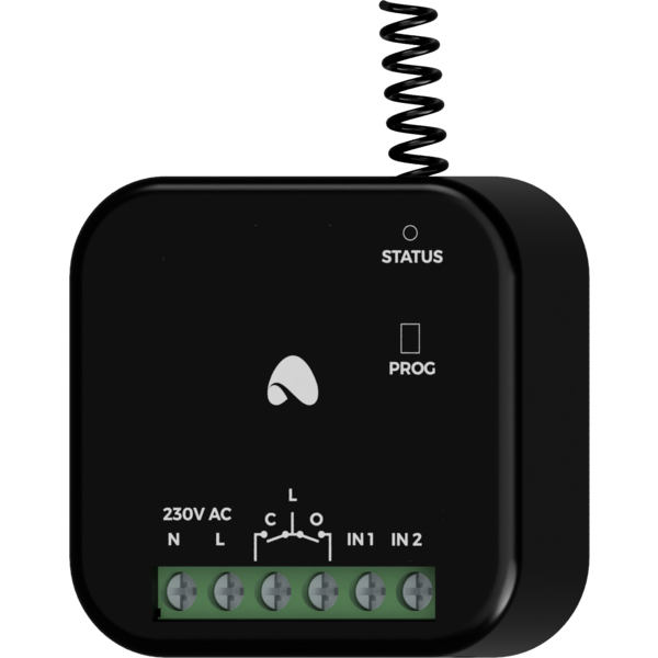
The module has a connector with screw terminals. It enables the connection of device’s power lines, signal lines to AC inputs and loads of relay outputs.
One of the contacts of each of the relays is connected to the power phase of the module.
On the front of the module there are signalling LED diodes. The green LED with the label STATUS indicates the status of communication on the Ampio LoRa interface.
The programming of the module is executed using the Ampio Designer tool. It allows modifying the module’s parameters and defining its behaviour in response to signals directly available to the module. It also provides access to all the information coming from all the devices present within the building automation bus.
Before starting configuration activities, it is necessary to pair the device with the module acting as the Ampio LoRa base station in the wired part of the building automation installation. To do this, using the Ampio Designer software, put the base station module into search mode for modules from the WL group. While the search mode is active, press the pairing button three times on the activated radio module. If the operation is successful, the found device will appear in the list of paired wireless modules in the Ampio Designer software.
It is not recommended to use more than 8 Ampio LoRa wireless modules per one base station module. Installing more modules may result in excessive load on the wireless network and improper functioning of the system.
Programming the rules for which the WL-REL-ROL1p module is to be an executive device, is defined during the configuration of the base station module. In order to create rules whose triggering depends on the state of the WL-REL-ROL1p module, it is necessary to add it to the device list as a virtual device.
By default, the inputs status of the WL-REL-ROL1p device is not broadcast within the wired part of the building automation bus installation. This behavior can be modified using the Ampio Designer configurator software, as part of the configuration of the device parameters available in the module settings of the Ampio LoRa base station.
As it is the case in other modules supporting the functionality of the roller shutter and blinds' drive controller, information about the beginning and end of the controlled device’s movement is broadcast within the building automation bus. However, in the case of the WL-REL-ROL1p module, information about its progress is not transmitted.
Internal rules of the module, i.e. the rules whose triggering depends on the state of the module’s own inputs, while their outcome applies to the module’s own outputs, are defined within the parameters of the module. Modification of the WL-REL-ROL1p device parameters is possible in the settings of the Ampio LoRa base station with which the device is associated.
By default, each WL-REL-ROL1p module implements the following internal rules:
These rules can be removed or modified at the device’s configuration stage.
Dimensions expressed in millimeters.
 Click to enlarge and open in a new tab.
