The image above is for illustration purpose only. The actual module may vary from the one presented here.
Module M-RDN-5s is a component of the Ampio system. Required voltage to power the module is 11 — 16V DC. The module is controlled via CAN bus.
The module enables powering the CAN bus in a redundant manner with the use of two independent power supplies. It also enables the bus to be split into 5 segments with individual short-circuit protection.
The module has two inputs for 11 — 16V DC power supplies. The voltage supplied by the power supplies is used to power the CAN bus connected to the device. Failure of one of the power supplies does not affect the other power supply to the bus. In order to use the functionality properly, it is necessary to ensure that each power supply is able to power the CAN bus on its own.
As part of the device, the voltage supplied by each of the power supplies is measured - the measurement result is made available in the building automation bus.
Some commercially available power supplies provide diagnostic signals. In particular, in the case of buffer power supplies, it can be the information about the consumption of the battery. The module has two inputs that go into an active state when they are shorted to ground, which enables the acquisition of these signals to the building automation system. These inputs are designed to receive signals generated by potential-free relay outputs or optocoupler outputs with a collector voltage greater than 5V.
The internal structure of the module inputs is presented in the figure below.

Generating a diagnostic signal within the power supply can be done in various ways. The module inputs are designed to work with potential-free relay outputs or optocoupler outputs. Before making the connection, check the documentation of the power supply to verify compatibility.
The module acts as a CAN bus distributor. It makes it possible to distinguish five network segments. Each of the segments has an independent overcurrent protection - in the event of a short circuit within the segment or the consumed current exceeding 2A, it is disconnected - in effect, it does not cause malfunctioning of any the other segments.
The module has an optocoupler diagnostic output. This output is active when two power supplies are connected to the device and their voltage exceeds 10.5V. In case the voltage of any of the power supplies drops below the limit value, the output is turned off.
The module is designed for mounting on a 35mm DIN rail. The module’s width is 105mm, 8 spaces/modules in DB. In order to start the module, it must be connected to the CAN bus. The bus of the Ampio system consists of four wires - two for power and two for communication between the modules.
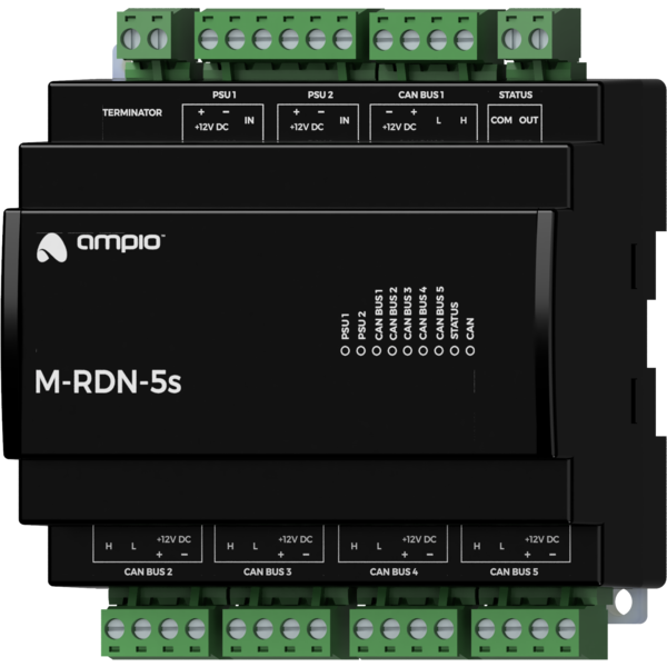
The module is equipped with five CAN bus connectors. The device also has a connector that allows for the connection of two power supplies with their potential diagnostic signals, and a connector for the module’s diagnostic output. In addition, the module has a connector that allows for convenient installation of a terminating resistor on the CAN bus data lines - its terminals are connected to the CAN H and CAN L lines of all bus segments.
On the front of the module there are signalling LED indicators. The green LED with the label CAN indicates the status of communication on the CAN bus:
Apart from the communication bus status LED, there are also seven red LEDs on the front of the device. They signal that the voltage of the power supplies and power lines for individual CAN bus segments is correct, i.e. exceeds 10.5V.
In the event of a voltage drop on any of the supply inputs below 10.5V, the device will signal the failure by short beeps every 2 seconds. This behaviour can be modified during the device’s configuration stage.
The module is programmed with the use of the Ampio Designer software. It allows you to modify the parameters of the module and define its behaviour in response to signals directly available to the module as well as general information coming from all devices present in the home automation bus.
Dimensions expressed in millimeters.
 Click to enlarge and open in a new tab.
