The image above is for illustration purpose only. The actual module may vary from the one presented here.
Module M-LED-s is a component of the Ampio system. Required voltage to power the module is 11 — 16V DC. The module is controlled via CAN bus.
The module acts as an OWA lighting bus controller.
The OWA lighting bus (One Wire Ampio) is a solution dedicated to controlling LED lighting. Each bus segment contains a controller and up to 16 lighting node drivers or LED lamps with integrated drivers. From the controller level, it is possible to smoothly adjust the brightness of light sources connected to each of the controllers. It is possible to control sets of light points or individual lights independently. It is also possible to implement the so-called staircase effect, i.e. smooth brightening and dimming of consecutive light points along the stairs, driveway, etc.
The OWA lighting bus consists of two wires - a ground wire and a wire that ensures communication between the controller and the drivers of a lighting node. Lighting node drivers also require a power line, hence the OWA bus is usually run with a three-wire cable.
With the use of several power lines, it is possible to connect to a single segment of the OWA bus lighting node drivers powered by different voltages. In such a case, however, care should be taken to properly equalise the ground potentials of each of the power supplies, i.e. to connect the grounding of the power supplies.
The M-LED-s module also enables diagnostics of the power line of lighting node drivers - if it is connected to the module, information about its voltage will be available within the building automation bus.
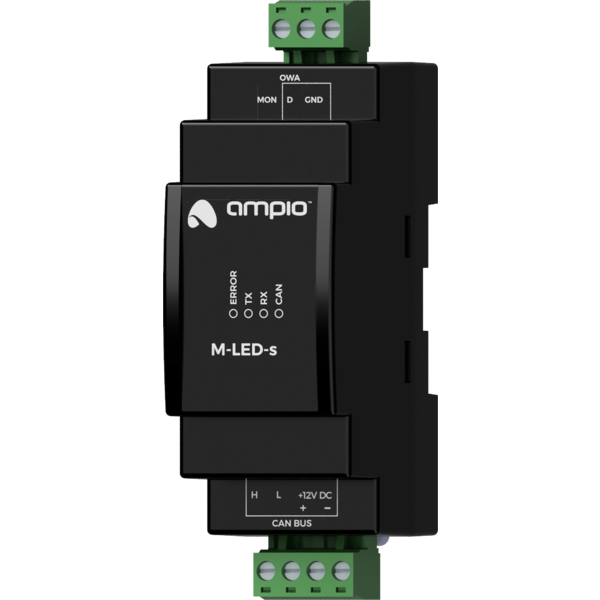
The module is designed for mounting on a 35mm DIN rail. The module’s width is 35mm, 2 spaces/modules in DB. In order to start the module, it must be connected to the CAN bus. The bus of the Ampio system consists of four wires - two for power and two for communication between the modules.
In addition to the CAN bus connector, the device has a connector that enables the connection of the OWA lighting bus.
In order to use the power line diagnostics functionality of lighting node drivers, it must be connected to the MON terminal - this connection, however, is optional.
On the front of the module there are signalling LED indicators. The green LED with the label CAN indicates the status of communication on the CAN bus:
Apart from the communication bus status LED, there are three red LEDs on the front of the device:
The module is programmed with the use of the Ampio Designer software. It allows you to modify the parameters of the module and define its behaviour in response to signals directly available to the module as well as general information coming from all devices present in the home automation bus.
Dimensions expressed in millimeters.
 Click to enlarge and open in a new tab.
