The image above is for illustration purpose only. The actual module may vary from the one presented here.
Module M-CON-CAN-s is a component of the Ampio system. Required voltage to power the module is 11 — 16V DC.
The module allows for galvanic separation of two CAN bus segments. This may be useful, for example, to separate the bus section serving devices installed outside the building from the main bus part, or to separate sections of the installation between which there may be a ground potential difference.
The use of the module to divide the network into smaller segments is also useful in the case of large networks in which the number of installed modules overloads the bus or if it is difficult to reduce the parasitic capacity of the bus through its termination.
Separation is carried out in an active way, hence the module can also act as an amplifier in the case of longer sections of the CAN bus.
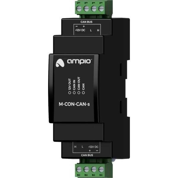
The module is designed for mounting on a 35mm DIN rail. The module width is 35mm, 2 spaces/modules in DB. In order to start the module, it must be connected to two separate sections of the CAN bus. The bus of the Ampio system consists of four wires - two for power and two for communication between the modules.
When using the module, only the transmission of logic signals between the separated bus sections takes place - the module does not share the power line between the sections. For the galvanic separation properties to be maintained, both sections must be powered by separate power supplies.
On the front of the module there are signalling LED indicators. The green LED with the label CAN indicates the status of communication on the primary side CAN bus (bottom connector):
Apart from the LED indicating the communication bus status, there are also three red LEDs on the front of the device:
The M-CON-CAN-s module is configured via the lower CAN connector.
Dimensions expressed in millimeters.
 Click to enlarge and open in a new tab.
