Description of Node-RED features: Node-RED is a data flow programming tool that allows you to easily create interactions between different devices and services. You can use it to integrate with smart TV, TEDEE lock, etc.
Risk warnings: Node-RED is a programming tool that requires adequate technical knowledge. It is the responsibility of the user to understand the logic of the programme created in Node-RED.
No technical support for application logic: Ampio does not provide technical support or any guarantees regarding the logic of user-created flows in Node-RED. It is a tool provided at the responsibility of the installer.
Liability for errors and losses: Ampio is not responsible for errors in the application logic, nor for any losses resulting from the use of Node-RED.
Encouraged testing: We encourage you to conduct small-scale testing before fully implementing a Node-RED-based project. This will help minimise potential risks.
Provision of helpful knowledge sources: We provide Node-RED documentation and other educational materials that can help you understand and use the tool effectively.
Please read the manual with understanding before using Node-RED. If you have any questions, please consult technical support.
To take advantage of the integration of the Ampio system and the Node-RED platform, you need to know the IP address of the server and the password of the user admin and run the interface via a browser.
You will find the interface of the Node-RED platform on port 1880 on the M-SERV module by typing IP:1880 into the browser (e.g. 192.168.1.2:1880).
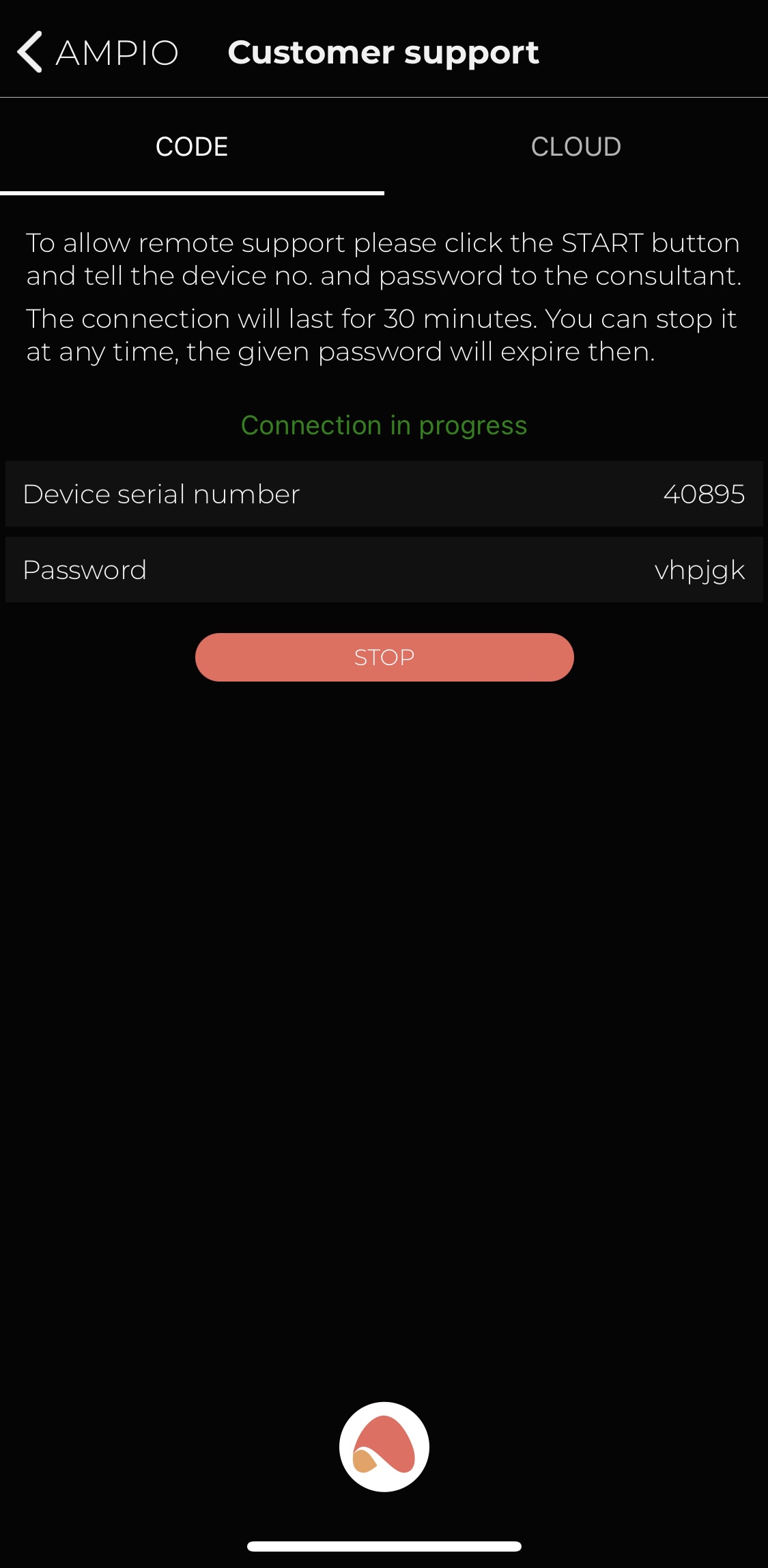
To run Node-RED via the cloud, you generate a serial number and password from within the Ampio UNI application. Click on the logo at the bottom of the screen, select Customer Support, and click START.
 Click to enlarge and open in a new tab.
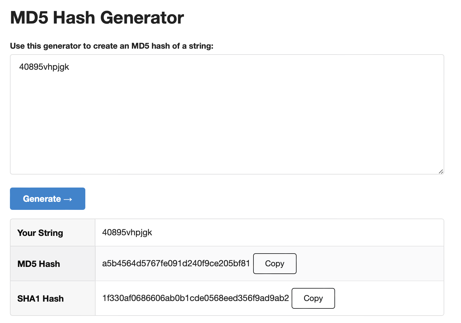
Next, find any page with the MD5 Hash Generator in a web browser, and enter the application-generated serial number and password in a single string.
 Click to enlarge and open in a new tab.
Copy the generated MD5 Hash.
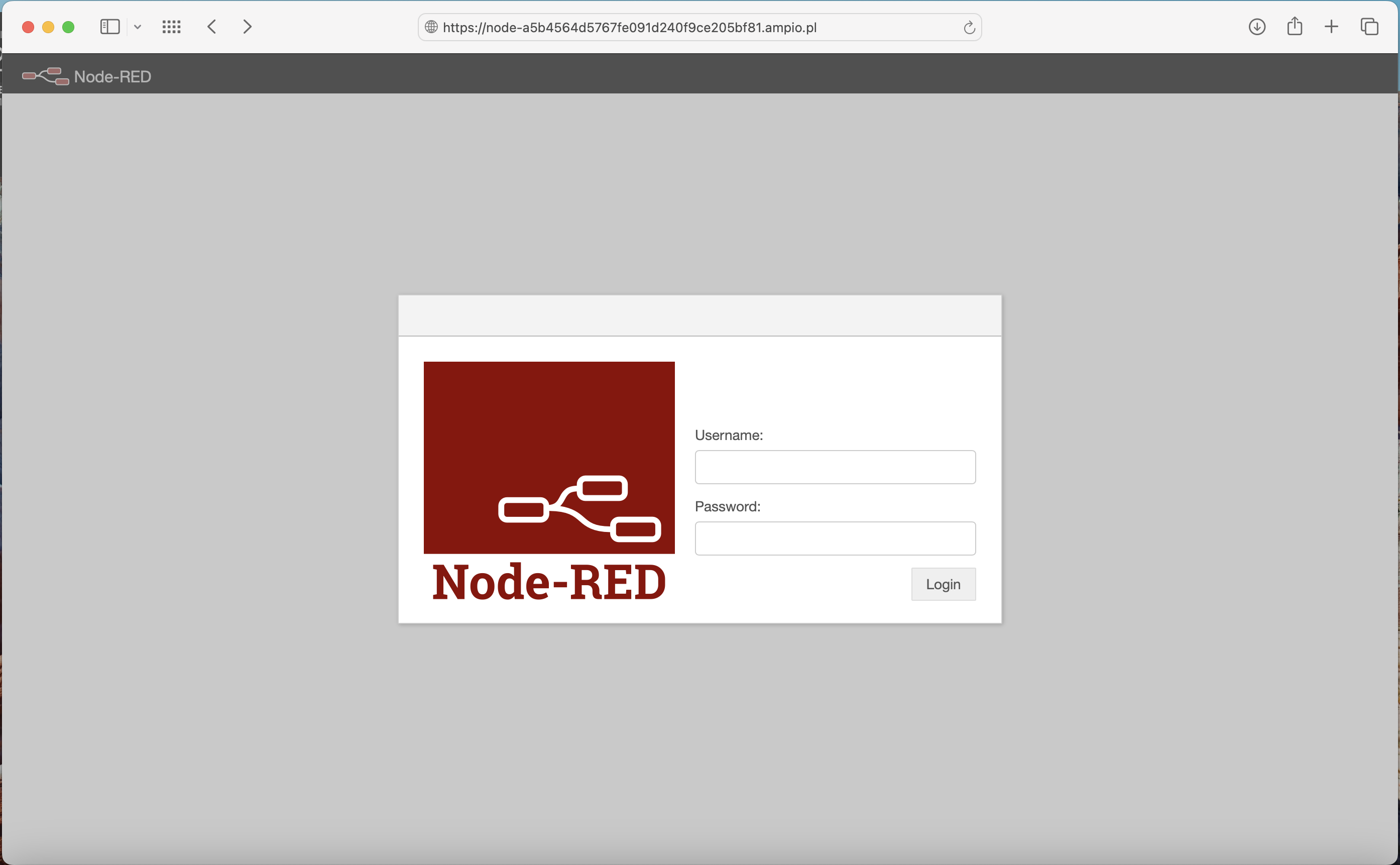
To access Node-RED remotely the following link must be used:
https://node-[generated MD5 Hash].ampio.pl
In our case:
https://node-a5b4564d5767fe091d240f9ce205bf81.ampio.pl
This is the address you need to paste into your browser:
 Click to enlarge and open in a new tab.
In order to use the functionality of integration between the Ampio system and Node-RED, you have to launch the interface in your browser and provide the server IP address, as well as the admin’s password.
The Node-RED interface can be accessed on M-SERV via port 1880 by entering IP:1880 (e.g. 192.168.1.2:1880) into the browser.
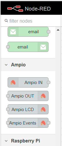
A selection of Node-RED nodes is on the left side of the interface, where you can also find Ampio’s predefined nodes that will facilitate creating dependencies.
 Click to enlarge and open in a new tab.
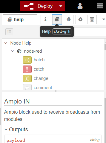
Each of the nodes has its own guideline in the Help tab.
 Click to enlarge and open in a new tab.
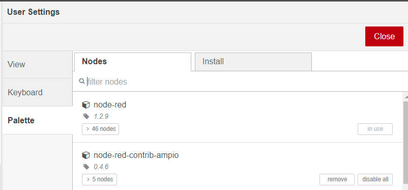
In order to ensure that the node-red-contrib-ampio library is up to date, enter Menu → Manage palette and check whether an update is available, or not. If an update is performed, you must reset the server.
 Click to enlarge and open in a new tab.
After using the first node from the Ampio library, it is worth it to perform a Deploy in order to check whether the node changed its status to connected, or not. Then, the node’s menu should be open, the magnifying glass icon selected and within 15 seconds a list of your devices should be displayed.
 Click to enlarge and open in a new tab.
If the node does not have a connected status, it might be necessary to configure it. Select the edit option right next to the Server field (the pencil icon). In the Connection tab in the Server field, enter the localhost, leave the port at 1883. In the Credentials tab, enter the login details from your Ampio www server.
 Click to enlarge and open in a new tab.
Once that is complete, click on Update, then Done and perform a Deploy.
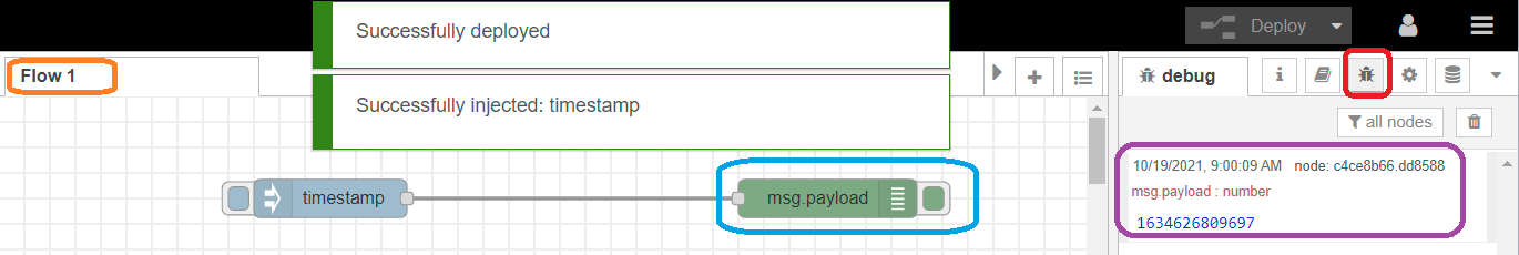
Node-RED enables code debugging and displaying information (data) on the right side of the interface. Examples are provided below:
 Click to enlarge and open in a new tab.
 Click to enlarge and open in a new tab.
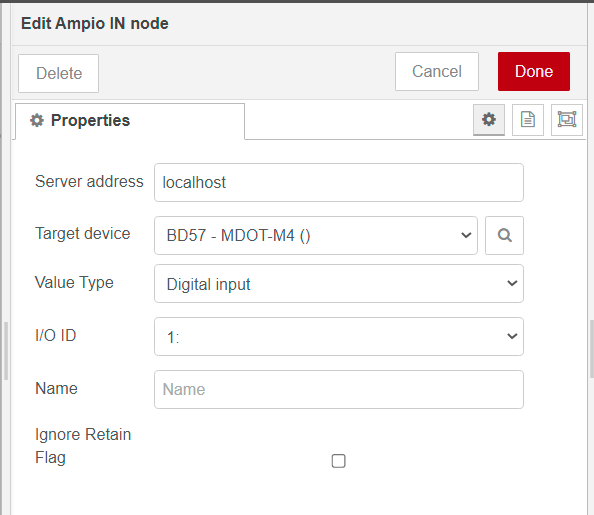
Parameters:
If the Ampio IN node is configured correctly, you will see “connected” under the node.
 Click to enlarge and open in a new tab.
Parameters:
If the Ampio OUT node is configured correctly, you will see “connected” under the node.
 Click to enlarge and open in a new tab.
Parameters :
The starting point is the top left corner of the screen. Its coordinates are LCD X=00 and LCD Y=00. Increasing the LCD X value will move the text towards the right side. Increasing the LCD Y value will lower the text, as shown below.
 Click to enlarge and open in a new tab.
 Click to enlarge and open in a new tab.
Parameters:
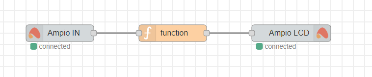
Here, we present an example of how to obtain the temperature from an Ampio module and display it, together with a description, on an M-DOT panel.
In the Ampio IN node, select, from which module you would like to get the temperature values, set the value type and the sensor’s ID.
 Click to enlarge and open in a new tab.
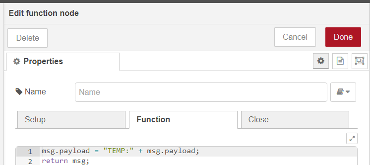
In the functional block, add a description using the Javascript language.
 Click to enlarge and open in a new tab.
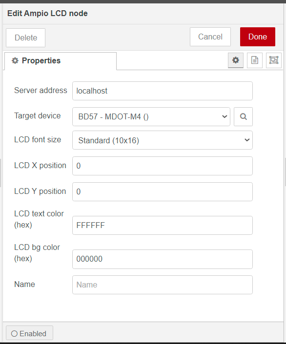
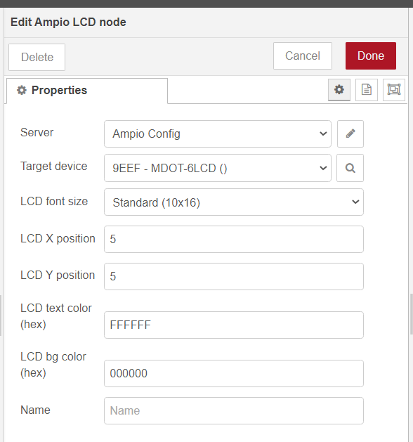
In the Ampio LCD node, select the M-DOT module and set up the position of text, the font size and colour, as well as the background colour.
 Click to enlarge and open in a new tab.
Connect the nodes and click deploy.
 Click to enlarge and open in a new tab.
The settings presented above will give you a white text ” TEMP: temperature value” in the middle of the screen on black background.
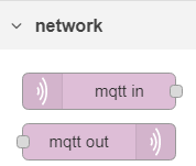
There is a possibility of integrating the Node-RED platform with the Ampio system without using predefined nodes. An MQTT broker will let you do that. With MQTT you can also track more events in the CAN network and control more advanced functions.
In order to do that, use nodes mqtt in and mqtt out.
 Click to enlarge and open in a new tab.
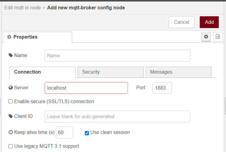
If you are using Node-RED installed on the M-SERV module, enter localhost in server properties. In other cases, credentials for login are the same as the ones used for the Smart Home Manager application and the server is provided with the use of an IP address. Once you are done, click on Add, Done and Deploy.
 Click to enlarge and open in a new tab.
Communication with the MQTT broker is mostly two-directional (from and to). A topic that begins with ampio/from allows for checking the status of devices. A topic that begins with ampio/to is used to control devices.
Examples of ampio/to usage:
ampio/to/<mac>/cmd – run the command
ampio/to/<mac>/raw – raw data frame
ampio/to/can/dev/list – a list of devices in the CAN network
ampio/to/event – broadcast the event
A list of commands:
| Command | Topic | Payload |
|---|---|---|
| set a single output | ampio/to/<mac>/o/<nr>/cmd |
on,off; 0..255 |
| RGB | ampio/to/<mac>/rgbw/<nr>/cmd |
off; 0..255,0..255,0..255 (on – for it to work) |
| RGBW | ampio/to/<mac>/rgbw/<nr>/cmd |
off; 0..255,0..255,0..255,0..255 (on – for it to work) |
| roller blinds | ampio/to/<mac>/o/<nr>/cmd |
0 – STOP; 1 – DOWN; 2 – UP |
| flags | ampio/to/<mac>/f/<nr>/cmd |
on,off; 0..255 |
| MRT- temperature | ampio/to/<mac>/rs/<nr>/cmd |
-99.9..155.0 |
| MRT-temperature day/night | ampio/to/<mac>/rsdn/<nr>/cmd |
temperature_day, temperature_night (example: 19,20) |
| MRT- operating mode | ampio/to/<mac>/rm/<nr>/cmd |
0 – calendar; 1 – MANUAL; 2 – MANUAL2; 3 – holidays; 4 – block |
Examples of the ampio/from topic:
| Type | Topic | Payload string | Payload example |
|---|---|---|---|
| temperatures | ampio/from/<mac>/state/t/<nr> |
-99.9 to 1000.0 (even more) | 21.5 |
| binary input | ampio/from/<mac>/state/i/<nr> |
0 or 1 | 1 |
| binary output | ampio/from/<mac>/state/o/<nr> |
0 or 1 | 1 |
| analogue input | ampio/from/<mac>/state/a/<nr> |
0 to 255 | 0 |
| binary input extended | ampio/from/<mac>/state/bi/<nr> |
0 or 1 | 0 |
| binary output extended | ampio/from/<mac>/state/bo/<nr> |
0 or 1 | 0 |
| rgb | ampio/from/<mac>/state/rgb/<nr> |
0..255,0..255,0..255 | 128,220,13 |
| flags | ampio/from/<mac>/state/f/<nr> |
||
| line 8-bit flags | ampio/from/<mac>/state/afu8/<nr> |
0..255 | |
| line 16-bit flags | ampio/from/<mac>/state/afi16/<nr> |
-32768..32767 | |
| MRT – temperature | ampio/from/<mac>/state/rs/<nr> |
25.5 | |
| 8-bit analogue values (DALI, LED) | ampio/from/<mac>/state/au/<nr> |
0…255 | 234 |
| 16-bit analogue values (signed) | ampio/from/<mac>/state/au16/<nr> |
0…65536 | |
| 16-bit reduced by 10K | ampio/from/<mac>/state/au16l/<nr> |
0…6553.6 | 23.4 |
| 32-bit values, e.g MODBUS | ampio/from/<mac>/state/au32/<nr> |
0…4 294 967 296 | 1234 |
If it is not indicated which data type should be used to send the values, the information is sent with the string type.
If you want to check all the available information in the system, use the mqtt in node, set the topic to ampio/# and connect debug. Then, click Done and Deploy. The data should appear in the debug window.
 Click to enlarge and open in a new tab.
If you would like to check the data from one, selected module, set the topic to ampio/from/MAC/# (e.g. ampio/from/ABCD/#).
MAC address should always be entered without leading zeros.
Always use the local MAC address to control modules.
If you want to check the status of a field in an M-DOT module, set the topic to: ampio/from/3910/state/i/1, where:
In order to activate the first output in a device with the MAC address ABCD, set the topic to: ampio/to/ABCD/o/1/cmd , and payload to: on.
Both options presented below will bring the same result:
 Click to enlarge and open in a new tab.
Apart from controlling outputs with commands, there is also a possibility to create own texts on the M-DOT display with the use of API commands. In order to use them, select the topic RAW. It might be necessary to update the software of the M-DOT module.
Control via API can be divided according to different LCD displays’ dimensions, as follows:
The term API is used in this guide in the context of sending commands from the MQTT broker to the touch panel display. It is not an API related to HTTP commands.
Commands to be displayed (for multi-screen displays):
The above character writing functions only work on screens of type Four icons and content. For them to work properly, the Actor fields in the settings of the respective screen must not be empty.
Functions not related to screens, always overwriting the current screen:
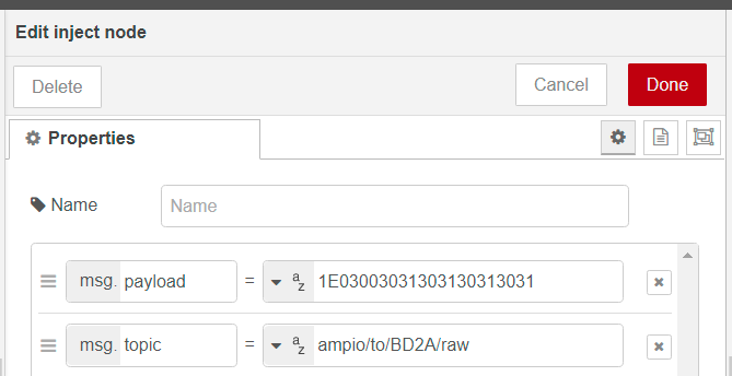
For example, sending:
msg.topic = ampio/to/ABAB/raw msg.payload = “1E03003031303130313031”;
changes the big row to 1 and 0 (in accordance with the ASCII code) on M-DOT with the MAC address ABAB.
Sending msg.payload = “2918000000003344AABB30313233” will return 0123 on the screen in specified colours.
Note: please mind the bit significance – LSB/MSB. Colours are coded in RGB565 standard, after generating colour codes it may be necessary to change the byte order.
Sending 291251000001… will start writing from 81 on the X-axis and 256 on the Y-axis. It is worth using a Windows calculator in a programmer mode for the calculations (hex 51 gives decimal 81, hex 100 gives decimal 256).
Sending 290C0000EF006A00D300000000 will draw a black rectangle extending over the whole width of the screen, between 1/3 and 2/3 of its height (it is the second row for the option 3 text rows).
 Click to enlarge and open in a new tab.
2-byte colours are saved in an RGB565 format.
Data that can be read from multisensor M-SENS:
ampio/from/<mac>/state/au16l/1ampio/from/<mac>/state/au16l/2ampio/from/<mac>/state/au16l/3ampio/from/<mac>/state/au16l/4ampio/from/<mac>/state/au16l/5ampio/from/<mac>/state/au16l/6ampio/from/<mac>/state/t/1Some of the control functions in Node-RED are made available through the RAW function.
The control topic is as follows: ampio/to/mac_adress/raw.
Below, you will find a list of examples of the functions that can be managed with the RAW topic:
Payload description:
Example: turns on flag 1 for 2 seconds in a device with the MAC=30EE
topic: ampio/to/30EE/raw
payload: 010001000000FFC80000
Payload description:
Example: set a specific colour
set: mac=33CD, colour R=255, G=255, B=0, W=0;
topic: ampio/to/33CD/raw
payload: 0200FFFF0000
Payload description:
Example: Ustaw flagę 0 na wartość 128.
topic: ampio/to/1907/raw
payload: 7AF98000 (string)
Payload description:
Example: Set the 0 flag to the value 4660.
topic: ampio/to/1907/raw
payload: 79F2341200 (string)
Payload description:
Example: Open the first roller blind.
topic: ampio/to/1907/raw payload: 31F90200 (string)
Payload description:
Example: Roller shutter number 3 at 0 percent.
topic: ampio/to/1907/raw payload: 31E00200 (string)
The function works in the MQTT broker version 4.25.1.
Payload description:
Example: Broadcast the temperature of 22 degrees as 11001055 address into the bus.
topic: ampio/to/broadcast/55/t payload: 22 (number)
Please, bear in mind that not all modules support the above-mentioned functionalities. We recommend checking in the Ampio Designer whether a given module supports, for example, 16-bit flags, or not.