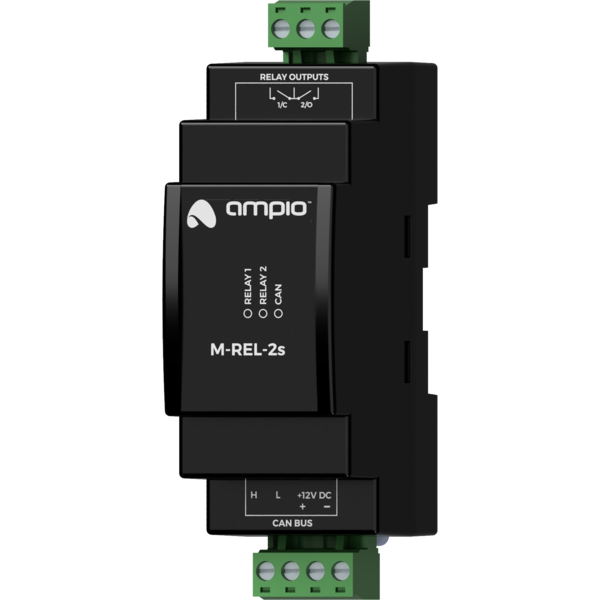
The image above is for illustration purpose only. The actual module may vary from the one presented here.
Module M-REL-2s is a component of the Ampio system. Required voltage to power the module is 11 — 16V DC. The module is controlled via CAN bus.
The module has two relay outputs and supports the functionality of a controller for the roller shutters and blinds’drives.
The module has relay outputs that enable switching on resistive and inductive loads. The module relays are normally open. The table below shows the permissible operating parameters of the relays depending on the nature of the load.
| The nature of the load | Maximum supply voltage | Maximum long-term permissible current |
|---|---|---|
| AC1: Resistive or moderately inductive AC loads | 250V AC | 16A |
| AC15: Inductive AC loads | 250V AC | 1.5A |
| DC1: Resistive or moderately inductive DC loads | 30V DC | 16A |
| DC13: Inductive DC loads | 30V DC | 2.5A |
One of the contacts of each of the relays is connected to a common terminal.
The module outputs are not intended for controlling sockets due to the possibility of connecting a receiver that exceeds the current capacity of the module. It is possible to connect the module to a socket after connecting it to an external contactor.
As part of the module configuration, it is possible to activate the functionality of a roller shutter and a blind drives' controller. This mode is intended for the control of devices powered by electric motors with a variable direction of movement and a limited movement range. For example, roller shutters and blinds' drives. However, this mode can also be used in other devices of a similar nature, such as, e.g. gates.
In the controller mode for roller shutters and blinds' drives, pairs of the device’s relay outputs work as a single compound output dedicated to controlling a single connected device.
The controller mode for roller shutters and blinds' drive is designed to control devices with built-in limit switches that disconnect the drive’s power supply when the ends of the range of motion are reached.
In the primary operation mode of the relay outputs, they are controlled by switching on or off individual outputs. In the case of pairs of relays operating in the roller shutters and blinds' drive controller mode, the control is performed by closing and opening commands or by setting the opening level. When it comes to blinds, it is also possible to set the position of slats.
During operation, the module estimates the state of the controlled device, i.e. the degree of opening and the position of slats (if applicable). This information is available within the building automation bus and is used internally to perform control in terms of the degree of opening or deflection angle of the slats.
A single pair of relays operating in a controller mode for roller shutters and blinds' drives can only be connected to a single drive. Any other connection may result in incorrect operation of the device, as well as permanent damage to both, the module and the drive.
The dimensions of the module enable its installation in a standard junction box. In order to start the module, it must be connected to the CAN bus. The bus of the Ampio system consists of four wires - two for power and two for communication between the modules.
In addition to the CAN bus interface, the device has a relays output connector. One of the contacts of each of the relays is connected to a common terminal.
On the front of the module there are signalling LED indicators. The green LED with the label CAN indicates the status of communication on the CAN bus:
Apart from the diode that indicates the status of the communication bus, on the front of the device there are also four red diodes indicating the status of the relay outputs.
The module is programmed with the use of the Ampio Designer software. It allows you to modify the parameters of the module and define its behaviour in response to signals directly available to the module as well as general information coming from all devices present in the home automation bus.
If the functionality of the roller shutters and blinds' drives controller is used, each connected device should be calibrated. The calibration is performed by defining the time parameters of full opening and closing, and the time parameters of the rotation of slats of the blinds (if applicable).
Dimensions expressed in millimeters.
 Click to enlarge and open in a new tab.
