The image above is for illustration purpose only. The actual module may vary from the one presented here.
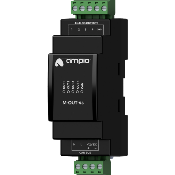
Module M-OUT-4s is a component of the Ampio system. Required voltage to power the module is 12 — 16V DC. The module is controlled via CAN bus.
The module has four voltage analogue outputs.
Voltage analogue outputs allow for integration with devices that have voltage control inputs compatible with the 0 — 10V DC, 1 — 10V DC, 0 — 5V DC standard, e.g. lighting fixtures, recuperators, inverters, etc.
The voltage of analogue outputs can take values in the range of 0 — 10V DC. The maximum load of a single output is 20mA.
The module is designed for mounting on a 35mm DIN rail. The module’s width is 35mm, 2 spaces/modules in DB. In order to start the module, it must be connected to the CAN bus. The bus of the Ampio system consists of four wires - two for power and two for communication between the modules.
In addition to the CAN bus connector, the device has a connector that allows for the connection of cables to four voltage analogue outputs.
On the front of the module there are signalling LED indicators. The green LED with the label CAN indicates the status of communication on the CAN bus:
Apart from the diode that indicates the status of the communication bus, on the front of the device there are also four red diodes indicating the state of the analogue outputs.
The module is programmed with the use of the Ampio Designer software. It allows you to modify the parameters of the module and define its behaviour in response to signals directly available to the module as well as general information coming from all devices present in the home automation bus.
Dimensions expressed in millimeters.
 Click to enlarge and open in a new tab.
