The image above is for illustration purpose only. The actual module may vary from the one presented here.
Module M-IN-AC4s is a component of the Ampio system. Required voltage to power the module is 11 — 16V DC. The module is controlled via CAN bus.
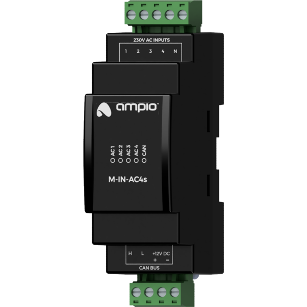
The module has four AC inputs.
The module has inputs that go into an active state when they are connected to an alternating voltage in the range of 110 — 250V AC. These inputs can be useful for phase presence detection or integration with devices with AC outputs, e.g. PIR or microwave presence detectors. They can also be used to connect classic light switches or other devices with potential-free contact outputs.
The AC inputs are galvanically separated from the low-voltage circuits of the module and the CAN bus.
The module is designed for mounting on a 35mm DIN rail. The module’s width is 35mm, 2 spaces/modules in DB. In order to start the module, it must be connected to the CAN bus. The bus of the Ampio system consists of four wires - two for power and two for communication between the modules.
In addition to the CAN bus connector, the device has a connector with screw terminals, enabling the connection of four AC lines to the module inputs.
On the front of the module there are signalling LED indicators. The green LED with the label CAN indicates the status of communication on the CAN bus:
Apart from the LED that indicates the communication bus status on the front of the device, there are also 4 red LEDs indicating the status of the AC inputs.
The module is programmed with the use of the Ampio Designer software. It allows you to modify the parameters of the module and define its behaviour in response to signals directly available to the module as well as general information coming from all devices present in the home automation bus.
Dimensions expressed in millimeters.
 Click to enlarge and open in a new tab.
