The image above is for illustration purpose only. The actual module may vary from the one presented here.
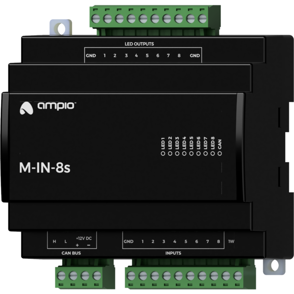
Module M-IN-8s is a component of the Ampio system. Required voltage to power the module is 11 — 16V DC. The module is controlled via CAN bus.
The module has eight ground detecting inputs, eight LED outputs and a 1-Wire interface.
The module has inputs that go into the active state when they are shorted to ground. They can be used in the case of any devices with potential-free contact outputs, e.g. wall switches, reed switches, buttons, switches, etc. They can also be used for integration with devices with potential-free relay outputs or optocoupler outputs with a collector voltage greater than 12V.
The module has low-current LED outputs. Each of the outputs provides a voltage of 5V through a built-in series resistor.
The module is equipped with a 1-Wire interface connector that allows to connect up to 6 digital Dallas DS18B20 temperature sensors. The temperature measurement result is available for all devices operating within the building automation bus. It may turn out to be particularly useful for purposes related to temperature regulation, or to present the measurement result on touch panels and in a mobile application.
The total length of the 1-Wire bus cable to which the temperature sensors are connected cannot exceed 15m.
The module is designed for mounting on a 35mm DIN rail. The module’s width is 105mm, 5 spaces/modules in DB. In order to start the module, it must be connected to the CAN bus. The bus of the Ampio system consists of four wires - two for power and two for communication between the modules.
In addition to the CAN bus interface, the device has two connectors with screw terminals. One of them allows for connecting eight signal lines to ground detecting inputs and up to 6 digital Dallas DS18B20 temperature sensors. The second connector allows for connecting up to 8 LEDs.
On the front of the module there are signalling LED indicators. The green LED with the label CAN indicates the status of communication on the CAN bus:
Apart from the LED indicating the communication bus status, on the front of the device there are 8 red LEDs indicating the status of the LED outputs.
The module is programmed with the use of the Ampio Designer software. It allows you to modify the parameters of the module and define its behaviour in response to signals directly available to the module as well as general information coming from all devices present in the home automation bus.
Dimensions expressed in millimeters.
 Click to enlarge and open in a new tab.
