The image above is for illustration purpose only. The actual module may vary from the one presented here.
* The alarm inputs can also be used as classic binary inputs.
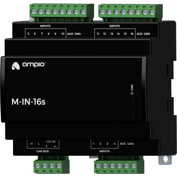
Module M-IN-16s is a component of the Ampio system. Required voltage to power the module is 11 — 16V DC. The module is controlled via CAN bus.
The module has sixteen alarm inputs.
The module has bi-state inputs that go into an active state when they are shorted to ground, allowing for the connection of any devices with potential-free contact outputs or optocoupler outputs. Such devices may include, in particular, reed switches and other alarm devices.
Depending on the configuration, alarm inputs can work with devices with the following types of contacts:
In addition to alarm applications, the inputs can be used as general purpose inputs in the case of any devices with potential-free contact outputs, e.g. wall switches, reed switches, buttons, switches, etc. They can also be used for integration with devices with potential-free relay outputs or optocoupler outputs with a collector voltage greater than 12V.
The module is designed for mounting on a 35mm DIN rail. The module’s width is 105mm, 6 spaces/modules in DB. In order to start the module, it must be connected to the CAN bus. The bus of the Ampio system consists of four wires - two for power and two for communication between the modules.
In addition to the CAN bus interface, the device has two connectors with screw terminals. They allow for connecting sixteen signal lines to alarm inputs.
In the case of loads with low power consumption, in particular small alarm sensors, it is possible to use the AUX terminals located on the alarm inputs' connectors, in order to power the devices. These terminals have the same voltage as the module’s supply voltage. The current consumption of each device connected to the AUX terminals must not exceed 100mA.
On the front of the module there are signalling LED indicators. The green LED with the label CAN indicates the status of communication on the CAN bus:
The module is programmed with the use of the Ampio Designer software. It allows you to modify the parameters of the module and define its behaviour in response to signals directly available to the module as well as general information coming from all devices present in the home automation bus.
Dimensions expressed in millimeters.
 Click to enlarge and open in a new tab.
