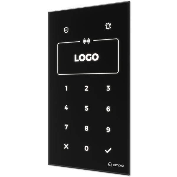
The image above is for illustration purpose only. The actual module may vary from the one presented here.
* The exact dimensions of the module depend on the variant of the glass edge finish selected when placing an order.
Module M-DOT-R14 is a component of the Ampio system. Required voltage to power the module is 11 — 16V DC. The module is controlled via CAN bus.
The module has fourteen sensor fields, an RFID card reader and a 1-Wire interface. It is designed to support functionalities of alarm and access control systems.
The touch panel sensor fields are capacitive buttons located behind the glass pane, which is the front of the module. Each sensor field is marked with a symbol engraved on the glass surface.
The condition for triggering an action associated with a given field can be pressing, holding, double-pressing, etc. A single field can initiate multiple actions depending on how it is triggered.
Each sensor field is illuminated by an RGB diode, which allows one to define any backlight colour. The backlight can be constant or change during the system operation, signalling the status of devices associated with the field, or any other information available in the building automation system.
There are colour status diodes above the two top sensor fields. In a similar fashion as it is with illumination, the diodes can indicate the status of devices associated with the field, or any other information available in the building automation system. The individual sensor fields that constitute a numeric pad are not designed to control any devices, which is why they do not have status diodes.
Sensor fields of the M-DOT-R14 module’s numeric keypad do not have status diodes.
The brightness of both, the symbols and the status LEDs, can be modified. The panel has a proximity sensor, thanks to which it is possible to define a weaker backlight when there is no interaction with the panel, and a stronger one, which gets activated when one brings a hand close to the panel.
The M-DOT panel calibration process runs automatically each time the power is switched on. To ensure optimum sensitivity and trouble-free operation of the device, it is essential to follow the guidelines below:
Final installation: Calibration must only be carried out after the panel has been fully installed in the mounting box. Testing the module ‘in your hand’ prior to installation prevents the correct reading of the base electrical capacitance, resulting in unstable operation of the touch panels.
Calibration procedure:
Install the panel in its intended location.
Reset the power supply (by switching it back on).
Note: Do not touch the front of the device for the first 3 seconds after start-up. During this time, the sensors stabilise in relation to the ambient conditions.
The module is equipped in an RFID card reader. It makes it possible to read cards that follow the ISO/IEC14443-3-A standard and is used for the implementation of access control functionalities. Card verification can happen in two ways.
At a configuration stage, it is possible to save a number of RFID card IDs that will later be recognised by the M-DOT-R14 module. When a card recognisable to the device is placed in front of its reader, it sends information about this event to the CAN bus. Such a piece of information can then be used by other devices of a specific building automation installation.
Also, it is possible to assign a schedule to each added card, which will define when a certain card should be recognisable. Schedules can defined in two ways - as a period of time with a start and end date, and as a list of the days of the week.
For the schedule functionality to be operational, there must be a module present in the bus that can serve as a source of information about time, e.g. a module from the M-SERV or M-RT families.
When an RFID card is placed in front of the device, its ID is broadcast to the CAN bus. Such information can be received by an IP integration module from the M-SERV family. The module, once it receives such a message, can take action to verify the ID and, possibly, perform any other actions if the ID is verified. This is what makes, for example, integration with external access control systems that share their API IP possible.
Sensor fields located under the RFID reader perform the function of a numeric keypad. The keypad is dedicated to functionalities related to PIN code access control. PIN code verification happens in two ways.
At a configuration stage, it is possible to define a number of 4-digit numerical codes. Entering a predefined code on the numeric keypad can trigger any action within a building automation system.
It is also possible to assign a schedule to each of the codes, which will be considered to be correct. Schedules can defined in two ways - as a period of time with a start and end date, and as a list of the days of the week.
For the schedule functionality to be operational, there must be a module present in the bus that can serve as a source of information about time, e.g. a module from the M-SERV or M-RT families.
Confirming a 4-digit sequence of numbers entered on the keypad will result in broadcasting the sequence into a building automation bus. Such information can be received by an IP integration module from the M-SERV family. The module, once it receives such a message, can take action to verify the PIN and, possibly, perform any other actions if the ID is verified. This is what makes, for example, integration with external access control systems that share their API IP possible.
The information can also be used by other integration modules, such as M-CON-232, which can send it further to an integrated, external control panel, as a request to arm or disarm an alarm.
The module can generate an event with a selected ID number based on the presentation of a valid card or the entry of a valid PIN code. If the event number is greater than 100, two events will be generated, one according to the configuration and the other equal to 100. Similarly, for events greater than 200, a second event with the number 200 is additionally generated.
The colour of the module’s front glass and the chamfer width of its edge are subject to personalisation.
Furthermore, the symbols of two sensor fields located above the RFID reader, as well as the contents of the frame that demarcates the place where an RFID card should be tapped, can be personalised. Symbols that constitute the numeric keypad can be selected from a pool of predefined variants.
The module is equipped with a buzzer that enables generating sound signals. By default, each press of the sensor field triggers a short buzzer sound. However, this behaviour can be modified.
In addition to confirming that the sensor field has been pressed, the buzzer can be used to signal any other events observable by the building automation system. The sound volume and type are defined at the device configuration stage.
The module is equipped with a 1-Wire interface connector that allows to connect up to 6 digital Dallas DS18B20 temperature sensors. The temperature measurement result is available for all devices operating within the building automation bus. It may turn out to be particularly useful for purposes related to temperature regulation, or to present the measurement result on touch panels and in a mobile application.
The total length of the 1-Wire bus cable to which the temperature sensors are connected cannot exceed 15m.
The panel can be mounted on a surface or it can be flush with the wall surface. Depending on the expected effect, a flush mounting plate or surface mounting frame is used. The frames are available in two variants - for panels with glass with and without chamfered edges.
Both in the case of flush and surface mounting, a standard junction box must be located behind the panel, inside which there will be connectors for the CAN bus and the 1-Wire interface. In the case of flush mounting, the box must be embedded in the wall at a greater than standard depth.
A detailed description of the installation of panels in both variants is available in the appropriate installer guides published on the Ampio knowledge base website.
On the back of the device, there is one red LED indicating the communication status within the CAN bus:
After the device is embedded in the mounting plate or frame, the LED is hidden.
The module is programmed with the use of the Ampio Designer software. It allows you to modify the parameters of the module and define its behaviour in response to signals directly available to the module as well as general information coming from all devices present in the home automation bus.
When planning the functionalities of the top sensor fields, it is crucial to bear in mind that they are located in a close proximity to the RFID card reader. This might mean, depending on the panel’s location in a room, the height of its installation, and typical usage scenarios of its users, that the fields are triggered unintentionally when an RFID card taps the panel. In order to minimise such a possibility, it is advisable to consider triggering an action as a response to, for example, a longer press on the field, instead of a short tap.
When planning the functionalities of the top sensor fields,it must be borne in mind that they can be unintentionally triggered by tapping an RFID card to the reader.
RFID cards' IDs and numerical PIN codes used for the purposes of internal verification are stored in shared memory. The maximum number of stored elements ranges from 60 to 113 - the ultimate limit is dependent on the number of defined access schedules.
Dimensions expressed in millimeters.
The panel consist of a glass front and a body with connectors and mechanical interfaces meant for mounting with the use of mounting plates or surface frames. The body is mounted in the center of the rear surface of the glass front with a margin of error appropriate for the production process.
The exact dimensions of the module front depend on the variant of the glass edge finish selected when placing an order.
In the dimensions diagram, the dashed line marks the area where the connectors of the device and its other elements protruding from the body are located. The outline of this area corresponds to the central opening in mounting plates and frames for panels. In the actual module, the CAN bus and 1-Wire interface connectors may be located in a different place than in the figure below, but within the marked area.
 Click to enlarge and open in a new tab.
The location of the device connectors on the connection diagram is indicative - in the physical module their location may be different.
