Ampio enables integrations via the Node-RED platform and makes a library of nodes available, which makes different types of integrations easier. The basics of integrations with the Ampio system carried out via Node RED are described in the Integration of the Ampio system with Node-RED manual.
This guide will take you through the steps of integrating your Ampio installation with Netio PowerPDU. For the purposes of this document, the NETIO PowerPDU 8QS model was used.
The first step is to connect your Netio PowerPDU to power and an Ethernet cable from your local network.
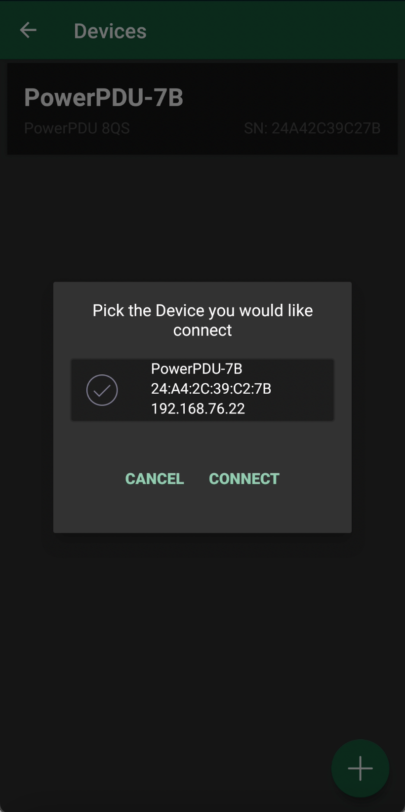
Then, you will need to find out the device’s IP address. In order to do that, download the NETIO Mobile application and connect your phone to the same network as the NETIO unit. Go to the Devices option in the app’s menu and click on Find device. The app will return information about your connected NETIO device, including the IP address.
 Click to enlarge and open in a new tab.
Save the IP address to use it later in Node-RED.
The NETIO PowerPDU provides various measuring tools for each of its outputs. For the purpose of integrating this functionality with your Ampio installation, you will need access to your Netio JSON configuration. It can be retrieved by pasting the following URL in your browser http://device-IP/netio.json. What you should see is presented in the figure below.
 Click to enlarge and open in a new tab.
More useful information on JSON structure in the context of NETIO products can be found on the PDU manufacturer’s website
In order to integrate NETIO PowerPDU with Ampio you must carry out two separate configurations in the Smart Home Manager, i.e. one for obtaining status from the NETIO device and another one for the controlling device.
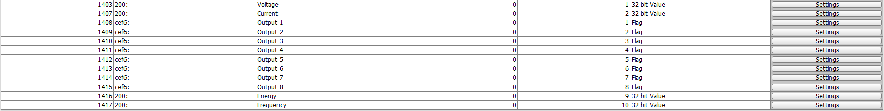
First, open your Smart Home Manager and navigate to “Objects” on the left side menu. Then, in the top bar, click on the “Add” button to add new objects. The number of objects you create here should correspond to the number of NETIO outputs that you wish to use, plus any values, e.g. voltage or current that you wish to measure. It might be helpful to change the Description of created objects to e.g. Netio output 1, Netio output 2, Voltage, etc.
 Click to enlarge and open in a new tab.
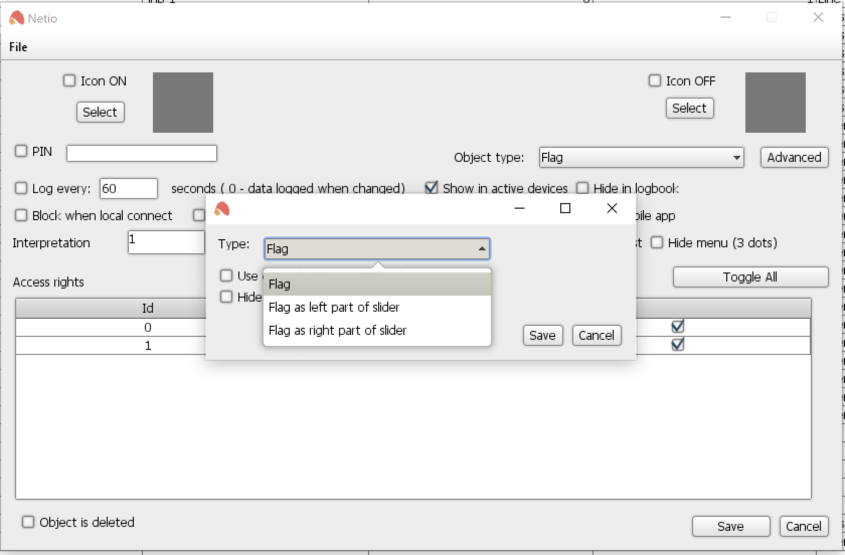
Next, go to each of the output objects' settings and set their object type to “Flag”.
 Click to enlarge and open in a new tab.
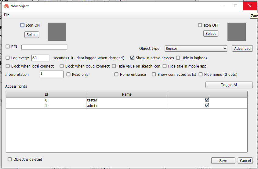
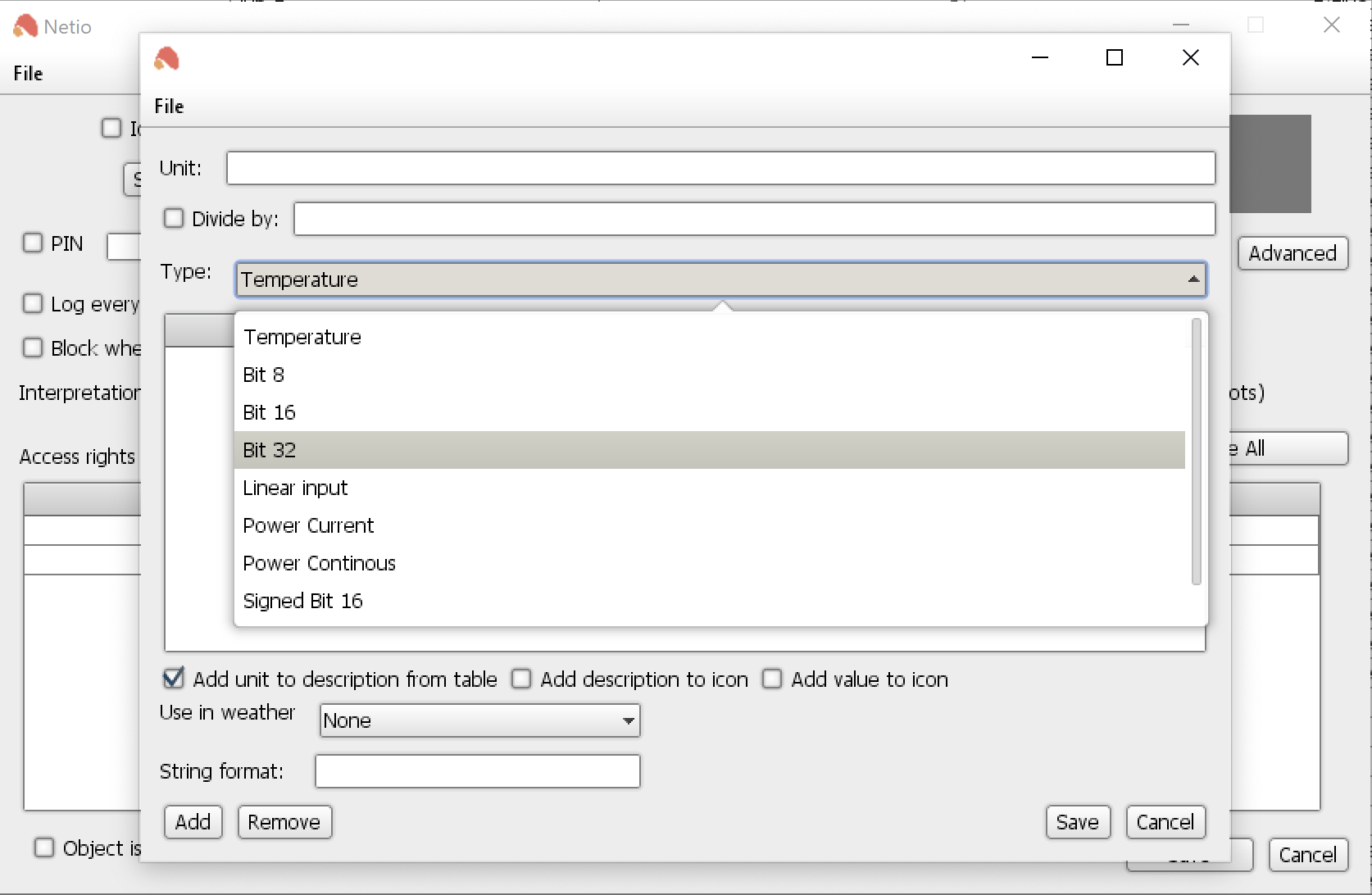
In a similar fashion, for the objects created to perform measurements, select the type “Sensor”, as shown below.
 Click to enlarge and open in a new tab.
Then, click the “Advanced” button and in the new pop-up window navigate to “Type” (which is, by default, set to temperature) and change it to “Bit 32”.
 Click to enlarge and open in a new tab.
Keep the Smart Home Manager handy - you will need to reference numbers of the set flags later in Node-RED.
Open Node-RED and log in using your credentials.
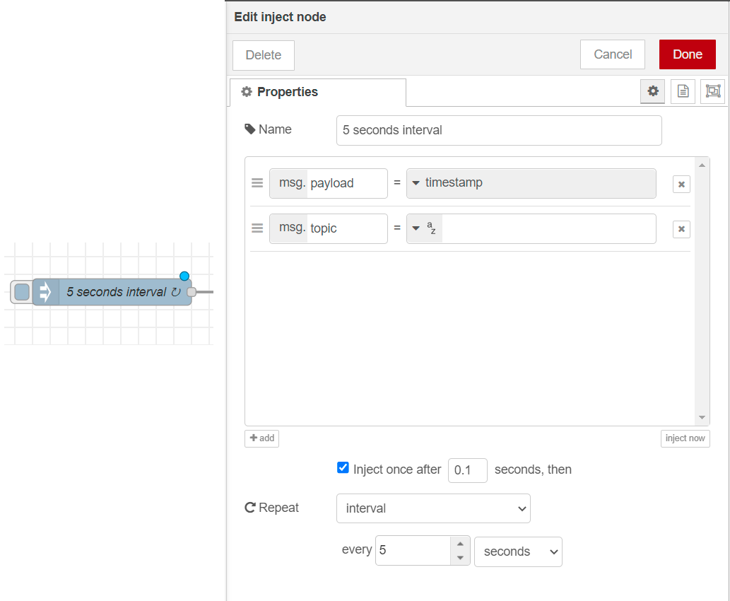
The Inject nodes allow you to inject messages into a flow, either by clicking the button on the node, or setting a time interval between injects. We will use the latter setting for the purpose of Netio integration.
First, drag an inject node from the pallette onto the workspace in Node-RED. Then, edit the node and set up 5-second intervals so that you can get the status of outputs and information about consumption every 5 seconds.
 Click to enlarge and open in a new tab.
Remember to add relevant names to the nodes you configure so that you can navigate between them easier.
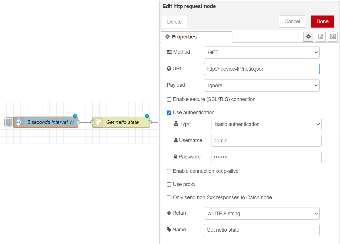
The next node to add to the workspace is an HTTP request node. Open its properties and set the Method to GET and paste http://device-IP/netio.json into the URL field. Then, set the Payload to Ignore. Use basic authentication as the authentication type. The required Username and Password are your Netio login credentials.
 Click to enlarge and open in a new tab.
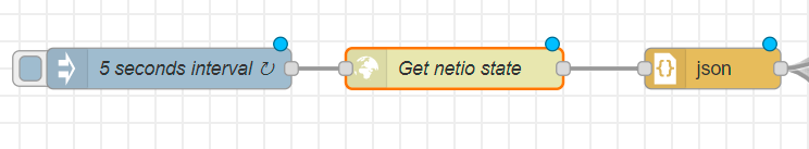
Next, you will need to add a JSON node, which is used to convert between a JSON string and a JavaScript object. The JSON node will, by default, detect what it is being given to convert.
 Click to enlarge and open in a new tab.
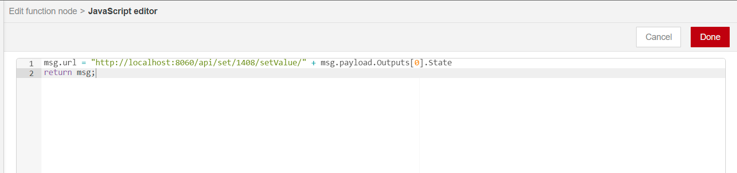
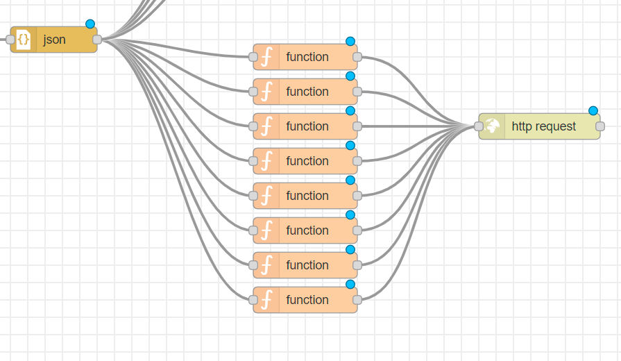
The Function node allows JavaScript code to be run against the messages that are passed through it. You will use the function nodes to receive information about the Netio outputs' state. Start adding the function nodes onto your workspace and configure them as follows:
In the On Message tab, add:
msg.url = (
    "http://localhost:8060/api/set/id/setValue/"
    + msg.payload.Outputs[0].State
);
return msg;
 Click to enlarge and open in a new tab.
The above-mentioned will return the sate of Output no. 1 of your NETIO device. In the same fashion, Outputs[1] in the code will provide the sate of NETIO Output no.2, etc.
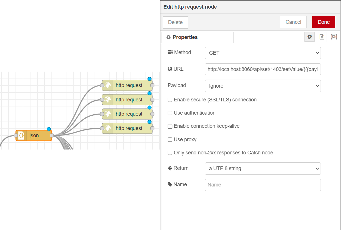
This node must be added now, if you want to read the measures of such electricity units as voltage, consumption, etc. on your NETIO device integrated with Ampio.
 Click to enlarge and open in a new tab.
The configuration is performed in a similar fashion described in the previous section, with the following exceptions:
__http://localhost:8060/api/set/1403/setValue/{{{payload.GlobalMeasure.Voltage}}}__
 Click to enlarge and open in a new tab.
The URL example above will get you the state of the voltage use, but you can replace it with other keywords from your NETIO JSON configuration to obtain readings of other electricity units, like current, load, etc.
 Click to enlarge and open in a new tab.
Finally, for you to be able to control and change the states of NETIO outputs via the Ampio UNI app, you must add the Ampio IN and Function nodes.
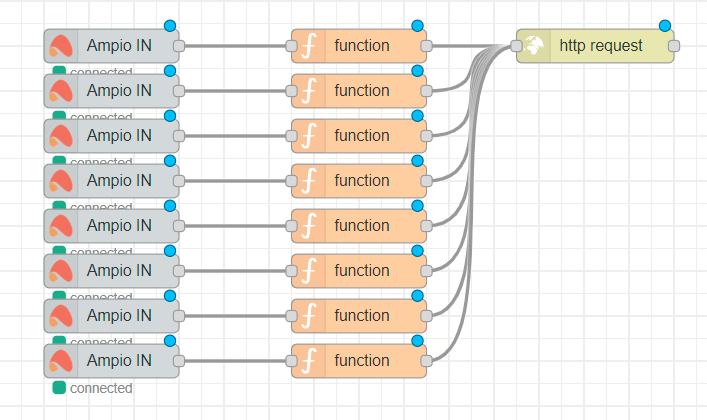 Click to enlarge and open in a new tab.
In the Ampio IN node, enter the flag number, which you have assigned earlier in Smart Home Manager.
In the Function node enter the following in the OnMessage tab:
//msg.payload = "{ "Outputs": [{ "ID": 1, "Action": 4 }]}"

msg.payload = { Outputs: [{ ID: 1, Action: msg.payload }] };
return msg;
The “ID” value will have to be changed in each function node for each output, for example, Output 1 will be “ID: 1”, Output 2 - “ID: 2, etc.
Configure the http request node in the same manner as you did earlier, but tick also basic authentication where you will enter your NETIO credentials.
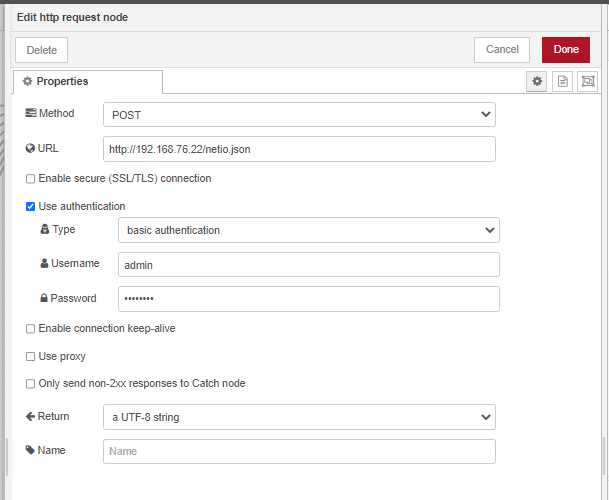 Click to enlarge and open in a new tab.
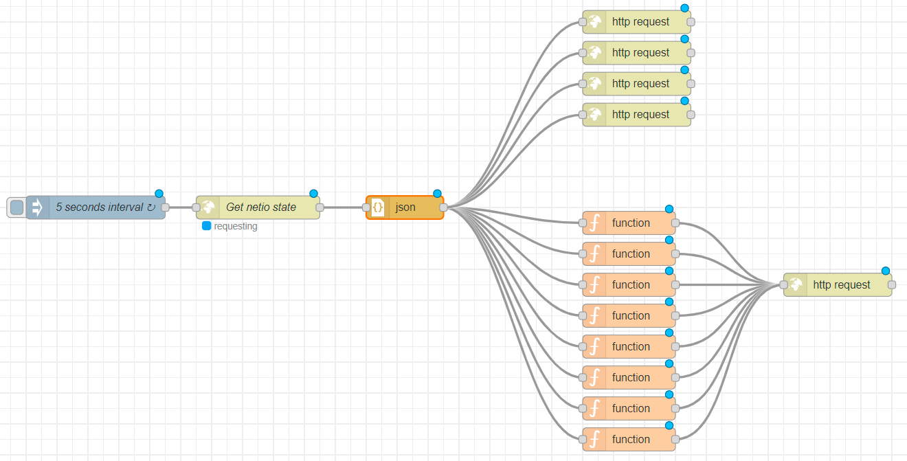
The configuration process is now complete. The figure below presents a workspace with concluded configuration for the NETIO PowerPDU to be integrated with the Ampio system.
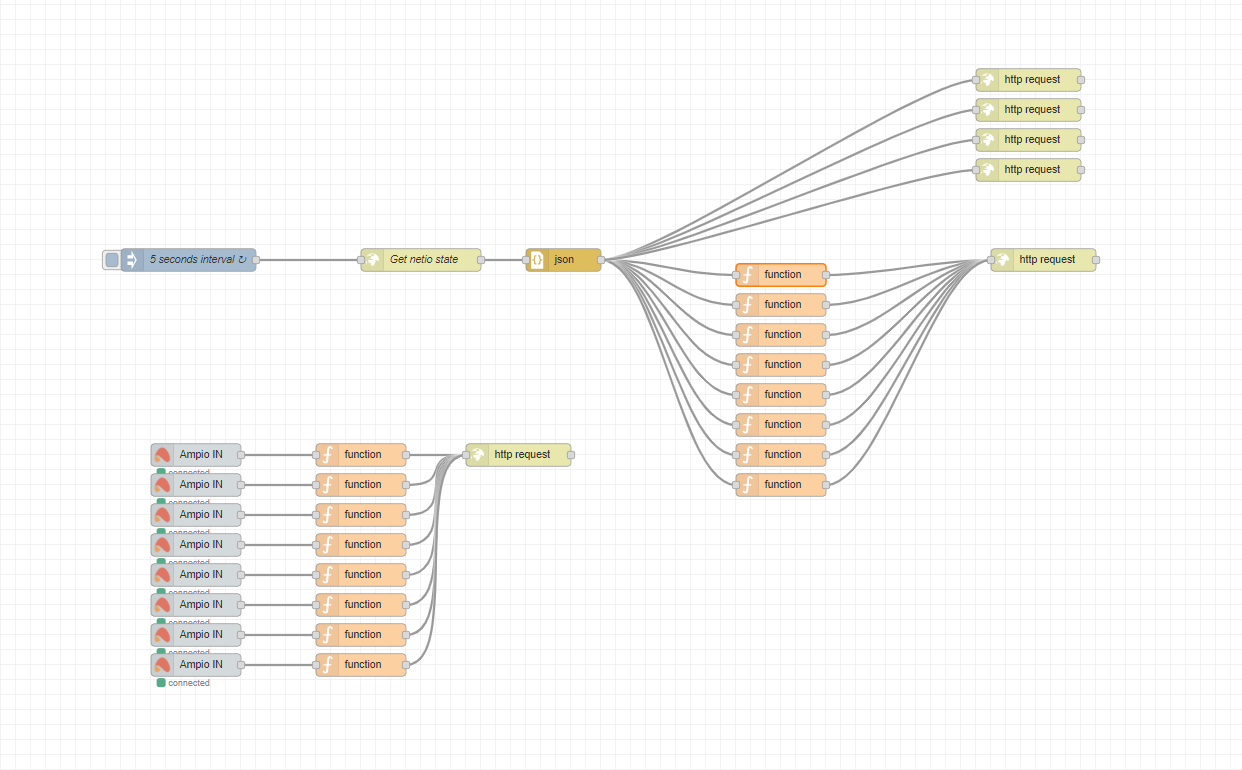 Click to enlarge and open in a new tab.
The last step is to click Deploy in Node-RED and the configuration will be saved on the installation’s M-SERV module.
In order to finalise this integration process and see its results in the Ampio UNI app, return to the Smart Home Manager and create a new group for “Netio” in the Grouping tab that can be found in the left side menu.
Then, select all the objects created in the Adding objects to Smart Home Manager step to the newly created Netio group.
Save and start managing your NETIO device from the Ampio UNI app.
