
Module firmware version 2.0 and newer is released first for the latest PCB versions. Availability of the update for older hardware depends on the specific module and does not cover all devices.
The Ampio Designer interface changes and the new method of updating server services, described in the first part of this guide, work regardless of the hardware version.
Update 2.0 marks the beginning of major changes in Ampio Designer, aimed at improving day-to-day work with the system. The current stable release brings primarily a completely refreshed interface and new diagnostic tools, such as CAN bus load statistics.
A much wider range of new features, covering module communication and firmware, logic creation, events and grouping, is tied to updating modules to version 2.0 and remains under active development and testing (see the notice below).
New versions of the module software are released gradually, with priority given to the latest hardware (PCB) versions. To check whether new versions are available for your devices, enable the beta version toggle in the Designer programme’s header menu.
 Click to enlarge and open in a new tab.
When this option is enabled, the system will notify you when updates are available for supported modules.
Tips for installers:
Ampio Designer has gained a new look, and the added functions shorten the configuration time of repetitive elements while making it easier to diagnose and supervise the installation.
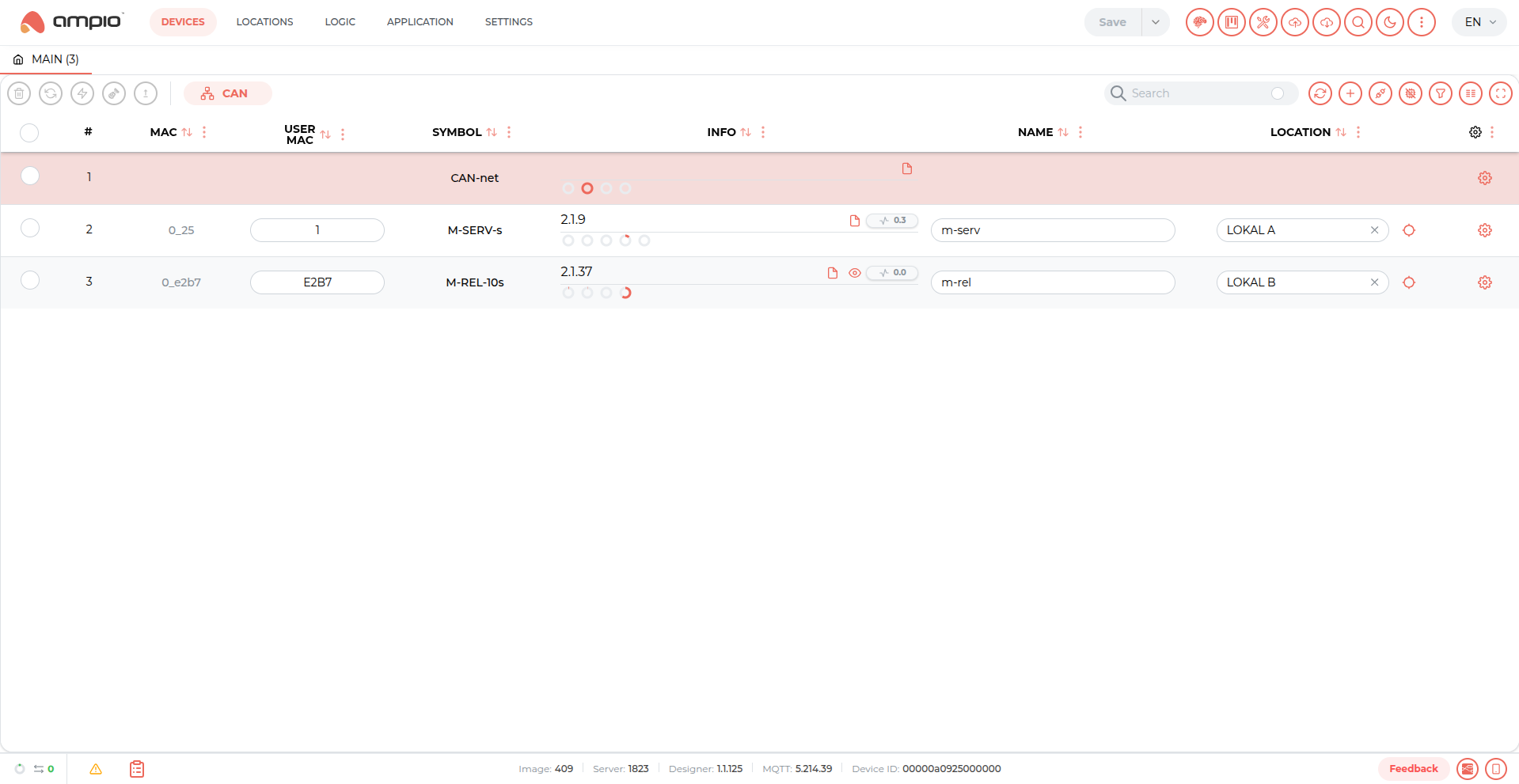 Click to enlarge and open in a new tab.
A new indicator on the bottom bar displays the current bus throughput, showing how heavily the system is loaded. This tool is useful for diagnosing problems, for example when logic created in the Node-RED environment unexpectedly causes a sharp increase in the number of messages, which may affect the stability of the system.
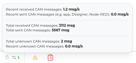 Click to enlarge and open in a new tab.
The same statistics are also available for individual modules in a condensed form, which makes it possible to quickly identify the devices generating the most network traffic.
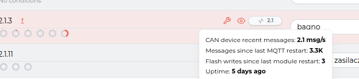 Click to enlarge and open in a new tab.
The condensed module statistics include:
The way server software is updated has been completely rebuilt. Previously each software package was updated separately. This required manually keeping versions consistent between components and gave no clear information about which set was the stable version and which was the test one.
The system is now updated as one coherent release version (ampio-release), containing a complete set of components tested together.
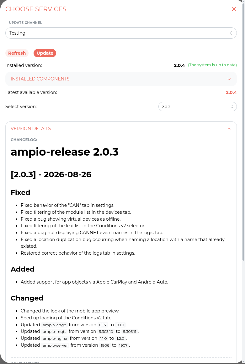 Click to enlarge and open in a new tab.
The new update window provides:
The Testing channel is intended for familiarising yourself with upcoming features on test installations. On end-customer installations we recommend using the Stable channel exclusively.
Most of the new features described below are tied to updating modules to version 2.0. This version is currently under active development and intensive testing.
We are making it available so that you can familiarise yourself with the upcoming capabilities early, however using it is entirely at your own risk:
To use Ampio Designer in version 2.0 the following is required:
All server services, including Ampio Designer, Ampio MQTT and Ampio Server, are part of a single release, so there is no need to verify their versions separately. The update procedure is described earlier, in the Server service updates (Ampio APT) section.
To ensure that all functionalities are available, we recommend always using the current stable versions.
In Ampio Designer 2.0 we introduce the concept of a LEAF. It is the elementary component of the system. It can be a physical input/output, but also a flag, a group or an event.
Updating the server software and updating the modules are two independent decisions:
To take full advantage of the new functionalities, the modules must be updated to version 2.1 or newer.
Before the update is performed, a message is displayed informing about its consequences, that is about a partial removal of the configuration.
Custom names stored on the module are preserved as long as the Restore names saved in the device after the update option stays selected. The conditions are deleted, which is why the same window offers the Download configuration and Download logic (PNG) buttons, the latter being a file with a graphical representation of the conditions previously stored on the module (with a larger number of conditions this is a ZIP archive with several images), which makes it easier to recreate them in the new system. The files are not downloaded automatically, the installer decides before confirming the update.
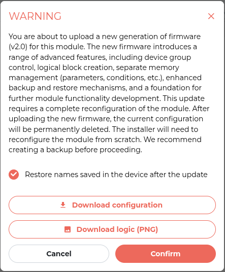 Click to enlarge and open in a new tab.
The changes described below apply only to conditions in version 2.0 and require modules with firmware version 2.1 or newer.
Conditions in version 2.0 have been rebuilt to make it possible to create complex logic.
A single trigger can now combine Leafs originating from different modules. To configure the parameters of a given trigger (for example the value or the duration required for activation), simply click the name of the leaf in the trigger.
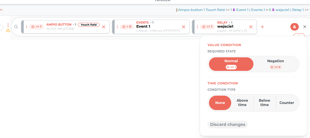 Click to enlarge and open in a new tab.
Within a single trigger block you can now choose the logic type, which decides when the block is triggered:
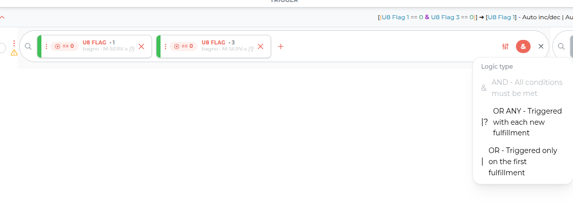 Click to enlarge and open in a new tab.
Linked conditions have been replaced by trigger blocks. Up to 3 trigger blocks can be created in total. The logic joining the individual blocks is always of the AND type. This means that in order to execute the action, the conditions defined in every block used must be fulfilled.
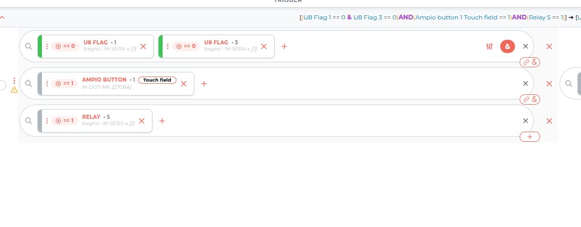 Click to enlarge and open in a new tab.
Value injection allows a value to be passed dynamically from one element (leaf) to another within the executed action. For example: a flag value set by the user in the Ampio UNI application can be “injected” as the target brightness level of the lighting in a condition.
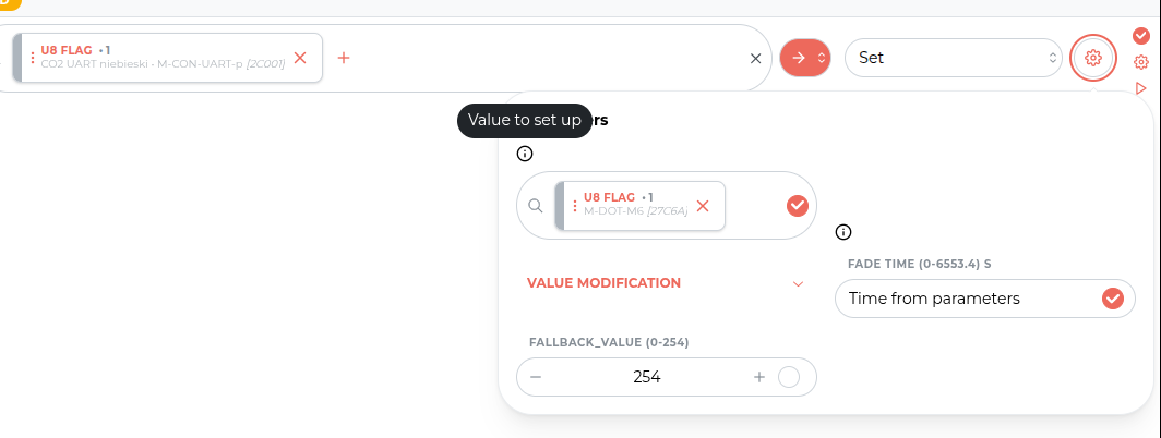 Click to enlarge and open in a new tab.
A folder system has been introduced, replacing the previous system of grouping conditions and allowing the logic in a project to be organised. Folders work exactly like those in a file system:
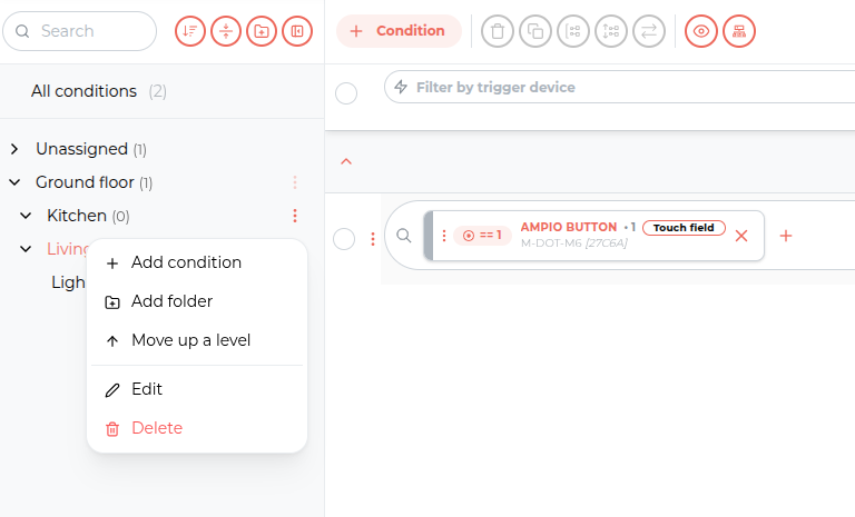 Click to enlarge and open in a new tab.
The logic tab offers a new way of presenting conditions, which allows the logic to be visualised as a graph. This changes the way relationships are analysed and created:
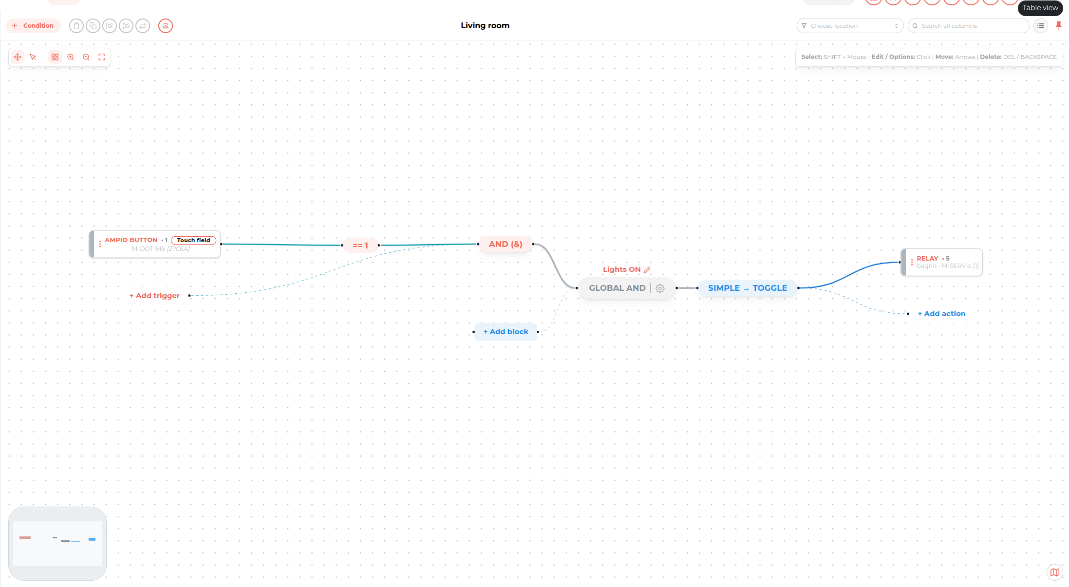 Click to enlarge and open in a new tab.
The block view is fully synchronised with the classic list view. Switching between them does not affect the logical structure of the condition, only the way it is presented and edited. Changes made on the graph are immediately reflected in the linear layout.
Below the current firmware version of a module, its memory sections are shown. This makes it possible to determine precisely how many resources are taken up by, for example, the current descriptions or the logic.
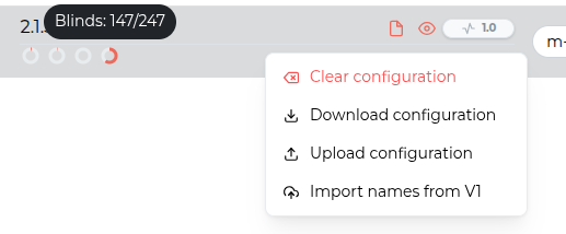 Click to enlarge and open in a new tab.
Between the custom name of the module and its firmware version there is a configuration menu. It allows you to:
If a module has registered an error, an ERROR marker appears next to its statistics in the device list. Thanks to this the problem is visible immediately at the level of the whole installation, without having to review the devices one by one.
The details are available after entering a given module, in the Errors tab. For each error the following is presented:
 Click to enlarge and open in a new tab.
The list can be sorted, searched and filtered, and the counters can be cleared in order to verify whether the error still occurs after changes have been made to the installation. Next to it there is a RAW tab with a raw preview of the diagnostic data.
An additional virtual module named CAN-net is visible in the devices tab. It is responsible for storing the descriptions of conditions and condition groups. This module is also used to configure events and the newly added group functionality.
Event configuration has been moved from the global settings to the CAN-net virtual module. New events are defined in the module’s tools tab. It is also now possible to trigger events manually directly from the functionalities tab, which allows the correctness of the logic to be verified efficiently.
 Click to enlarge and open in a new tab.
The key change in version 2.0 is the transition from a pulse-based model to a value-based one:
This approach allows a single event to be reused for different purposes. For example: one event, depending on the value assigned to it, can trigger different lighting scenes or control how far the blinds are opened.
The CAN-net module introduces the functionality of grouping Leafs, configured from the module’s tools. Groups make it possible to manage resources distributed across the system collectively.
 Click to enlarge and open in a new tab.
The following group types are available:
From the functionalities list of the CAN-net module it is possible to control the value of the created groups manually.
Because of the universal character of groups, the set of actions available for them in conditions is simplified compared with the functions offered for individual Leafs. This allows many different Leafs to be controlled consistently and reliably within a single group.
If advanced functions dedicated to a particular device type are required, we recommend controlling the individual Leafs directly within the condition.
Modules handling communication with external devices were previously presented as a single device, and all elements coming from the integration ended up in a shared functionalities list of the parent module.
Version 2.0 introduces child modules. The parent module is still responsible for all communication, both physically and in software. In the device tree, each integration connected to it receives its own separate device, containing only its own elements.
 Click to enlarge and open in a new tab.
This mechanism covers:
As a result, Leafs coming from the individual integrations do not mix with each other or with the functions of the parent module itself, which simplifies finding them while creating logic and organises the structure of the project.
In modules that support output mapping, a new Hardware tab has been introduced, organising the functions related to mapping and to the physical settings of the outputs.
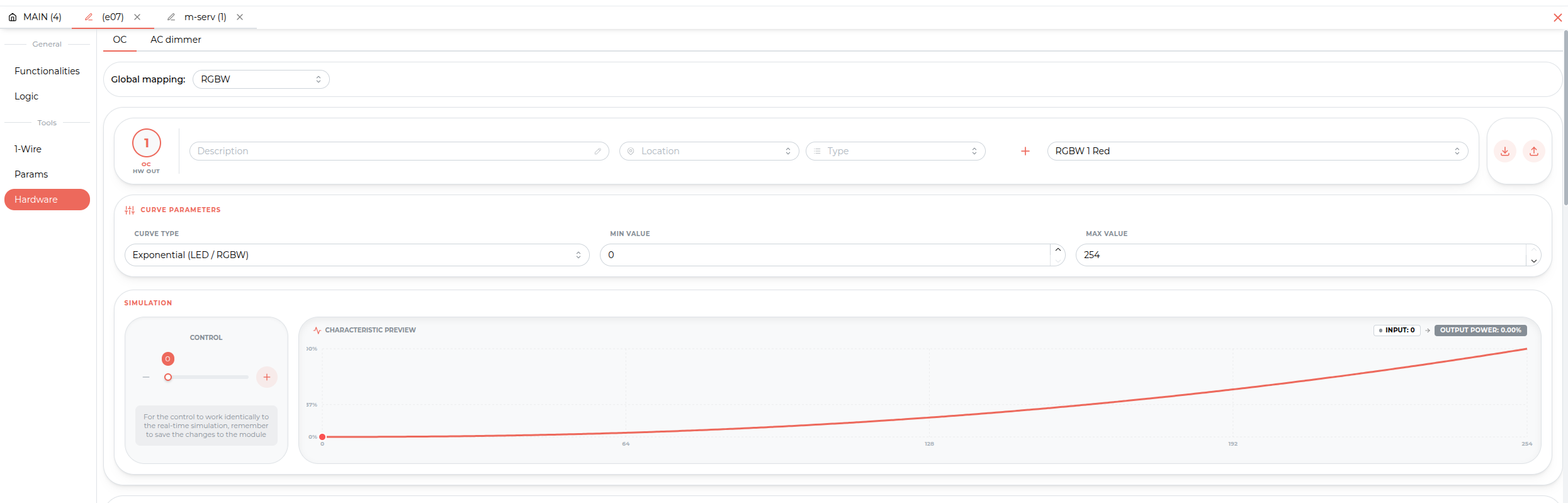 Click to enlarge and open in a new tab.
From this section it is possible to change the mapping of individual channels and to fine-tune their operating parameters, such as:
The way RGBW colour lighting is managed has been completely rebuilt and based on the HSV standard (Hue, Saturation, Value). In contrast to classic control of the individual channels (RGB), this model allows much more intuitive management of light.
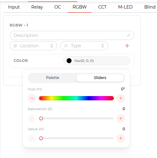 Click to enlarge and open in a new tab.
The new interface allows three parameters to be operated independently:
Modules equipped with 8 OC-type outputs (for example M-OC-C8s and M-INOC-8s) have gained the ability to handle two independent RGBW channels from firmware version 2.1 or newer.
Support for light sources with a variable colour temperature (CCT) has been rebuilt. The previous proportional control model has been replaced by a model based on physical parameters, which allows much greater precision.
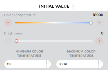 Click to enlarge and open in a new tab.
The most important changes include:
The server now also supports mapping OC outputs as CCT channels.
Support for blinds and venetian blinds has been extended with a wizard that measures the drive parameters automatically, and with a refreshed parameters panel.
The Auto-calibrate button opens an interactive wizard that guides the installer step by step through the process of configuring the drive. On the basis of the measurement cycles performed, all the key operating parameters of the blind are determined: the opening and closing times, the unsealing time and the dead times.
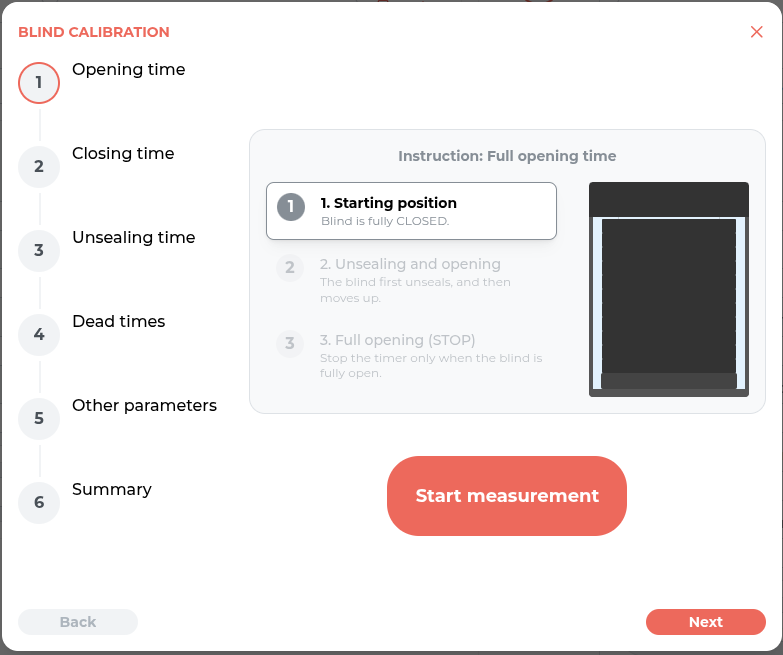 Click to enlarge and open in a new tab.
The parameters panel has been completely refreshed.
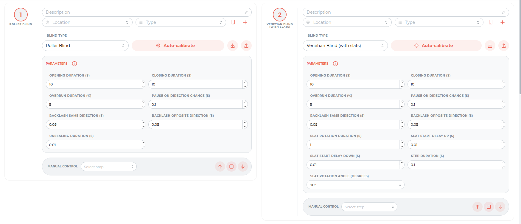 Click to enlarge and open in a new tab.
Key changes in the parameters:
Support for heating and cooling zones has been designed completely from scratch. The previous, relatively simple controller has been replaced by an extensive mechanism that makes it possible to describe the actual operation of a heating installation, with multiple heat sources, a schedule and separate handling of the floor temperature.
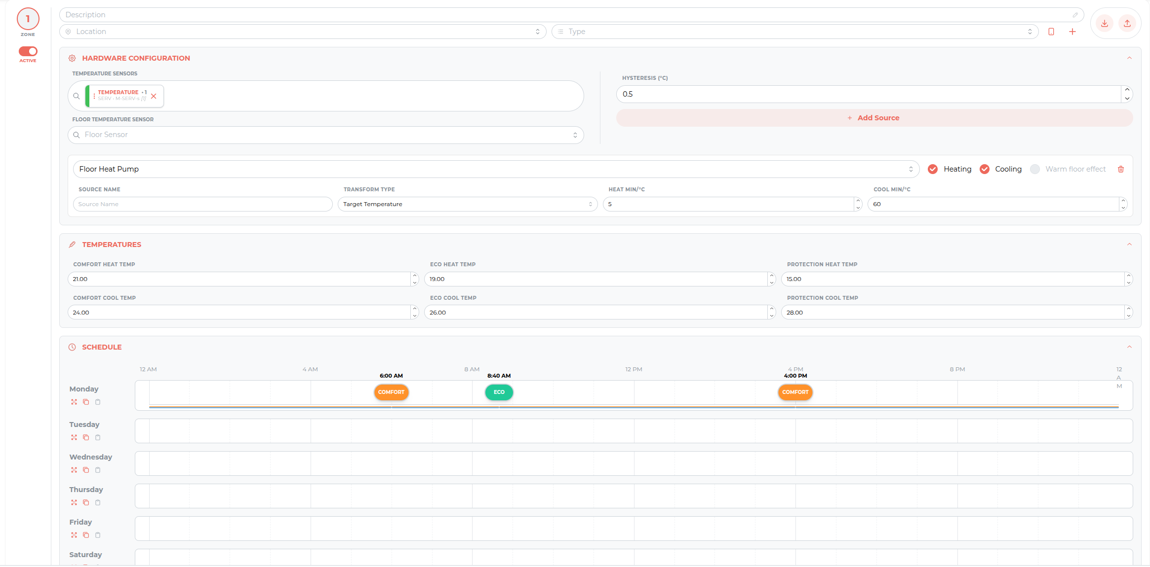 Click to enlarge and open in a new tab.
The most important new features:
Dedicated support for underfloor heating has been introduced, based on a separate floor sensor. Thanks to this the controller can simultaneously supervise two quantities: the air temperature in the room and the temperature of the floor itself.
This solution makes it possible to implement the warm floor effect. The floor is kept in a state of constant, minimal heating in order to preserve comfort when walking on it, regardless of whether the room has already reached the setpoint air temperature.
Operation in this mode is covered by safety limits which prevent the floor from overheating. This protects both the floor finish and the heating installation itself.
Version 2.0 introduces communication scripts, with which the installer independently defines how the module communicates with an external device. This makes it possible to handle practically any equipment controlled over RS-232, for example a projector or an AV receiver.
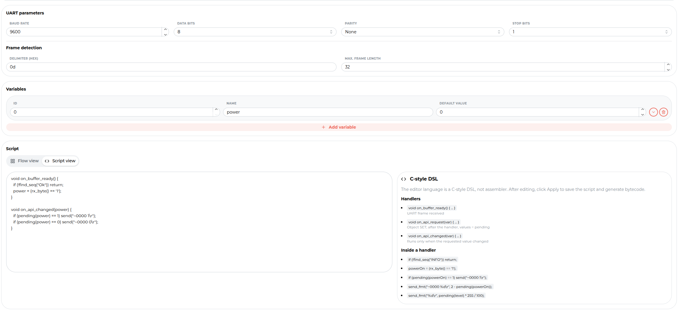 Click to enlarge and open in a new tab.
A script can be created in two views, switched at the top of the editor:
Above the editor there are the remaining configuration elements: the UART parameters (baud rate, data bits, parity, stop bits), frame detection (the delimiter and the maximum frame length) and the table of variables the script operates on.
Regardless of the chosen view, the script describes the full course of the communication: the form of the commands sent, the way the device’s responses are interpreted, and how they are linked to Leafs. Thanks to this the external device can be both controlled from within conditions and report its own state.
Communication scripts are also planned for the RS-485 bus and for further modules.
Support for the RS-485 bus has been based on the child modules mechanism described earlier. Each device polled over the Modbus protocol is added as a separate child of the parent module and has only its own Leafs.
The most significant functional change is individual transmission parameters. In previous versions the communication settings applied jointly to the whole bus, which forced the selection of devices working with an identical configuration. Now each child has its own set of parameters, so devices from different manufacturers, with different transmission requirements, can work on a single bus.
In addition, separating the devices into individual child modules organises the functionalities list. The Leafs of the individual meters, inverters or controllers do not mix with each other, which simplifies finding them while building logic.
The configuration of the displays in the touch panels has been completely redefined. The rigid layout of icons and text rows has been replaced by a widget system, which gives full freedom in designing the interface.
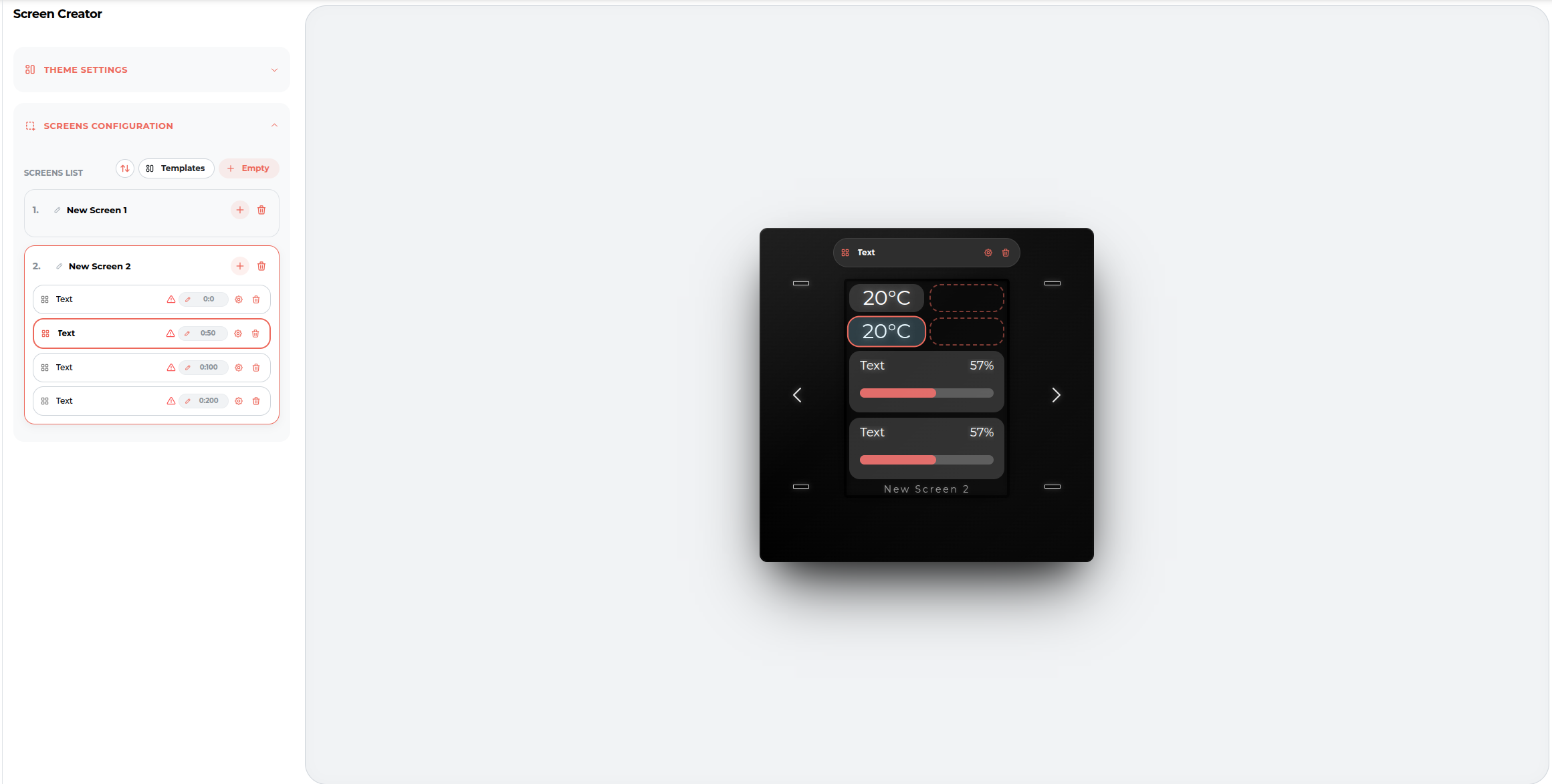 Click to enlarge and open in a new tab.
What does the new Screen Creator change?