The image above is for illustration purpose only. The actual module may vary from the one presented here.
Module M-IN-TCD3p is a component of the Ampio system. Required voltage to power the module is 11 — 16V DC. The module is controlled via CAN bus.
The module has three inputs for NTC temperature sensors with a resistance within the range of 5-20kΩ at 25°C.
The module has inputs that allow temperature measurement using resistive NTC sensors with a resistance ranging from 5kΩ to 20kΩ at a temperature of 25°C.
These sensors facilitate the implementation of accurate measurements in the ranges encountered in the context of ambient temperature measurements or central heating system monitoring. The availability of rugged and waterproof NTC probes makes them a common choice for monitoring the operating parameters of underfloor heating systems.
The dimensions of the module enable its installation in a standard junction box. In order to start the module, it must be connected to the CAN bus. The bus of the Ampio system consists of four wires - two for power and two for communication between the modules.
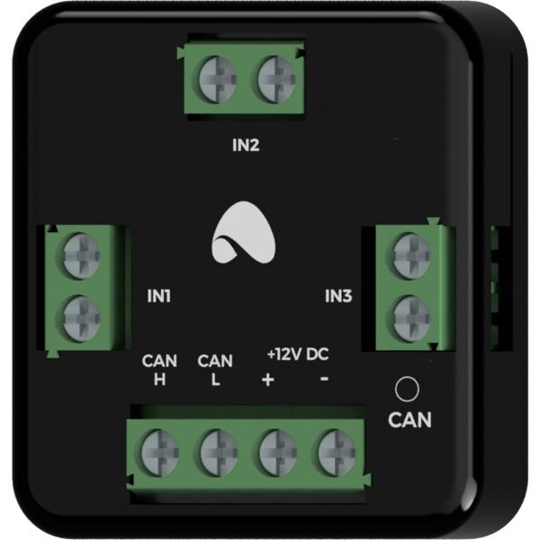
In addition to the CAN bus connector, the device has three connectors that allow one to connect NTC resistance sensors.
On the front of the module there are signalling LED indicators. The redl LED with the label CAN indicates the status of communication on the CAN bus:
The module is programmed with the use of the Ampio Designer software. It allows you to modify the parameters of the module and define its behaviour in response to signals directly available to the module as well as general information coming from all devices present in the home automation bus.
During the device configuration, it is necessary to provide the β constant value of the connected temperature sensors. Each of the sensors may have a different parameter value defined.
Dimensions expressed in millimeters.
The dashed lines mark the areas where the device connectors or its other elements can be located.
 Click to enlarge and open in a new tab.
