The image above is for illustration purpose only. The actual module may vary from the one presented here.
Module M-IN-RKE4-p is a component of the Ampio system. Required voltage to power the module is 11 — 16V DC. The module is controlled via CAN bus.
The module enables the reception of signals generated by Ampio wireless remote controls.

With the use of the module, it is possible to receive signals generated by Ampio wireless remote controls. It is possible to programme up to 64 remotes that support rolling codes.
Information about key presses of remote controls is broadcast by the device within the building automation bus.
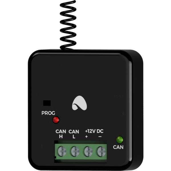
The dimensions of the module enable its installation in a standard junction box. In order to start the module, it must be connected to the CAN bus. The bus of the Ampio system consists of four wires - two for power and two for communication between the modules.
A cable, which constitutes an antenna, is led out of the casing of the device.
On the front of the module there are signalling LED indicators. The redl LED with the label CAN indicates the status of communication on the CAN bus:
Apart from the LED indicating the communication bus status, there is also a yellow LED on the front of the device. It signals the reception of signals from the programmed remotes and it serves as a pairing mode indicator.
The module is programmed with a special programmer, available for authorised technicians, and the Ampio Smart Home CAN configurator software. It allows you to modify the parameters of the module and define its behaviour in response to signals directly available to the module as well as general information coming from all devices present in the home automation bus.
On the front of the device, there is a hole with a button that is used to pairing remote controls with the device. To put the device into a pairing mode, press and hold the button until the yellow LED lights up. When the device is in a pairing mode, simultaneously press and hold the first and second buttons on the remote control that you are pairing. The correct process of pairing is signalled by the yellow indicator diode flashing. After pairing, the device remains in a pairing mode and it is possible to add more remote controls to it. To exit the pairing mode, press the pairing button.
To remove information about all previously paired remotes from the device, hold down the pairing button until the yellow signaling diode lights up and then goes off.
Remote controls can also be paired with the use of the Smart Home CAN configurator software.
Dimensions expressed in millimeters.
The dashed lines mark the areas where the device connectors or its other elements can be located.
 Click to enlarge and open in a new tab.
