The image above is for illustration purpose only. The actual module may vary from the one presented here.
Module M-DIM-1s is a component of the Ampio system. Required voltage to power the module is 11 — 16V DC. The module is controlled via CAN bus.
The module has one dimmable output.
With the use of the module, it is possible to control the light intensity of incandescent bulbs, halogens, dimmable LED bulbs and dimmable CFL fluorescent lamps. It is possible to control light sources powered through a transformer.
The maximum power of the receiver connected to the dimmable output is 300W. The input voltage ranging from 48V AC to 250V AC can be smoothly regulated.
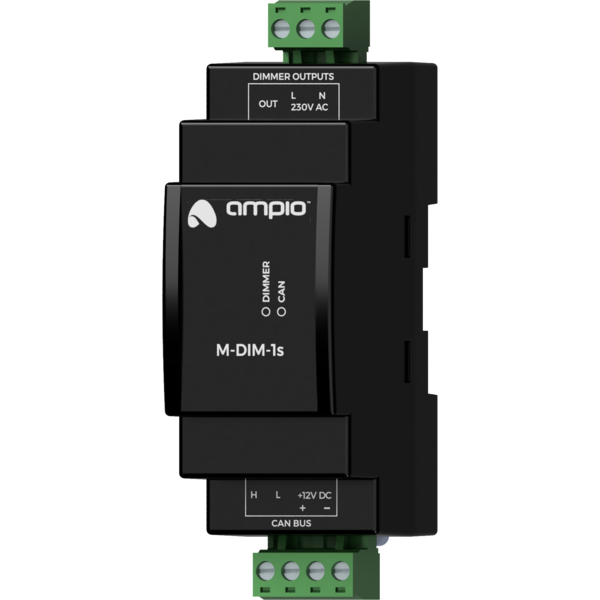
The module is designed for mounting on a 35mm DIN rail. The module’s width is 35mm, 2 spaces/modules in DB. In order to start the module, it must be connected to the CAN bus. The bus of the Ampio system consists of four wires - two for power and two for communication between the modules.
In addition to the CAN bus interface, the device has a mains voltage connector and a dimmable output.
On the front of the module there are signalling LED indicators. The green LED with the label CAN indicates the status of communication on the CAN bus:
Apart from the diode indicating the communication bus status, on the front of the device there is also a diode labeled DIMMER. It indicates the status of the dimmable output.
The module is programmed with the use of the Ampio Designer software. It allows you to modify the parameters of the module and define its behaviour in response to signals directly available to the module as well as general information coming from all devices present in the home automation bus.
Dimensions expressed in millimeters.
 Click to enlarge and open in a new tab.
