The image above is for illustration purpose only. The actual module may vary from the one presented here.
Module M-CON-WZ-p is a component of the Ampio system. Required voltage to power the module is 11 — 16V DC. The module is controlled via CAN bus.
The module acts as a base station for wireless modules.
Only one M-CON-WZ-p module can be present within an Ampio building automation installation.
The device acts as a base station for Ampio devices from the WZ group, communicating via the Ampio WZ wireless interface. As a base station, the device mediates communication between the wireless modules and other devices in the building automation installation.
As part of the installation activities, each Ampio WZ device must be paired with a module acting as a base station. To do this, enter the M-CON-WZ-p module into the search mode for modules from the WZ group using the Ampio Designer software. While the search mode is active, press the pairing button. If the operation is successful, the found device will appear in the list of paired wireless modules in the Ampio Designer software.
The dimensions of the module enable its installation in a standard junction box. In order to start the module, it must be connected to the CAN bus. The bus of the Ampio system consists of four wires - two for power and two for communication between the modules.
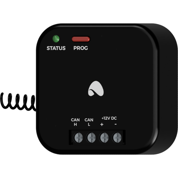
Outside the casing of the device is a cable which forms its antenna.
On the front of the module there are signalling LED indicators. The redl LED with the label CAN indicates the status of communication on the CAN bus:
The module is programmed with the use of the Ampio Designer software. It allows you to modify the parameters of the module and define its behaviour in response to signals directly available to the module as well as general information coming from all devices present in the home automation bus.
We do not recommend using more than 8 Ampio WZ wireless modules per base station module. Installing more modules may result in excessive load on the wireless network and malfunction of the system.
Dimensions expressed in millimeters.
The dashed lines mark the areas where the device connectors or its other elements can be located.
 Click to enlarge and open in a new tab.
