The M-CON-KNX-s module enables the Ampio bus to be integrated with KNX bus components. The module has outputs for both the CAN bus and the KNX bus. Please note that the KNX bus must be independently powered and programmed according to KNX standards. Physical and group addresses on the KNX side can be assigned e.g. via the ETS application.
The guide for the Ampio Designer tool applies to M-CON-KNX-s modules of PCB version 2 minimum, while the guide for the Smart Home Configurator is valid for PCB version 1.
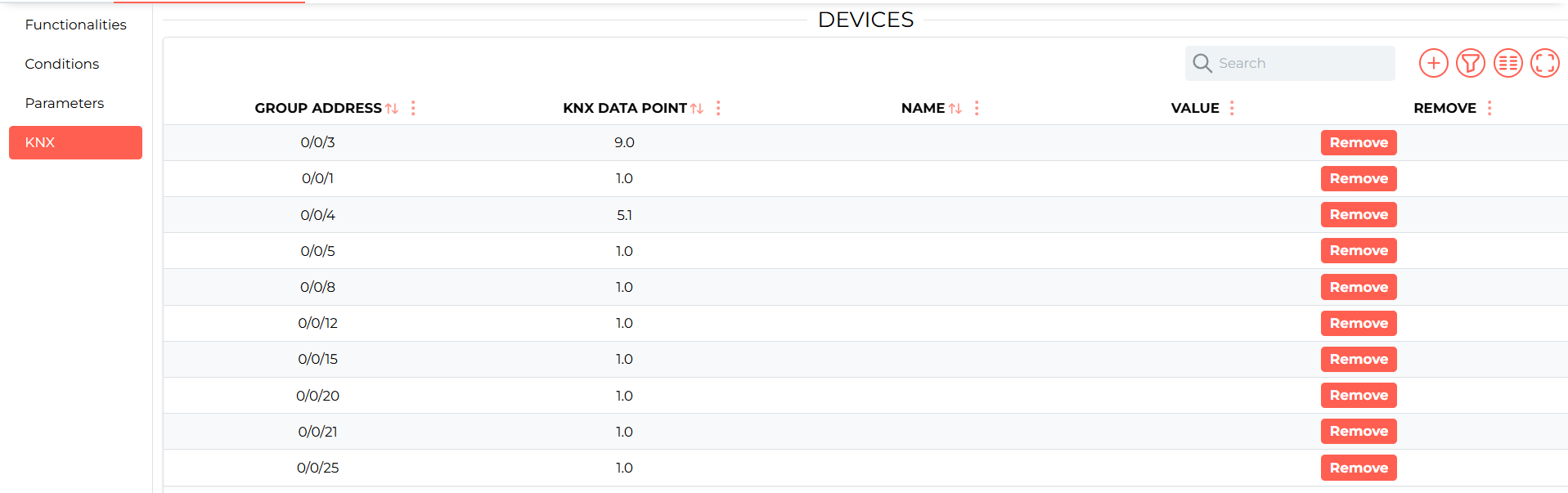
In order to read cyclic data from the KNX bus, a translation list must be configured. With the M-CON-KNX-s module connected, enter its settings using the cog icon and then go to the KNX sub-tab.
 Click to enlarge and open in a new tab.
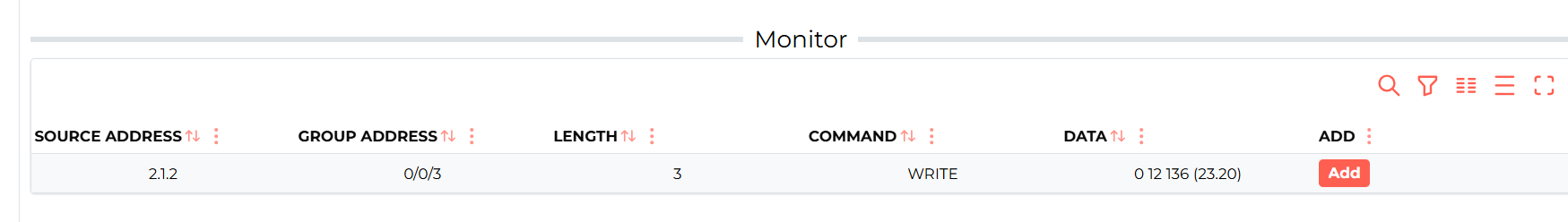
At the bottom, the Monitor window shows the telegrams that the module has received on the KNX bus.
 Click to enlarge and open in a new tab.
This allows us to quickly add a telegram to the list of translations using the Add button. The new translation will appear in the DEVICES window.
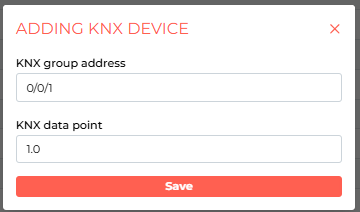
To add a translation manually, select the + icon in the top right corner and enter the group address and the data type according to the KNX standard.
 Click to enlarge and open in a new tab.
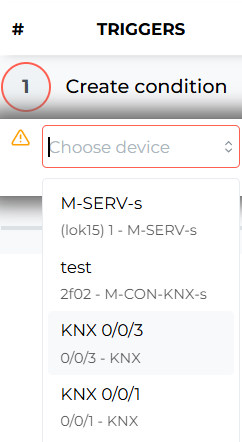
In the LOGIC tab it is possible to create conditions in both directions, i.e. information can be transmitted from the CAN bus to the KNX bus as well as the other way round.
In order to respond to data from KNX in the Ampio system, a condition has to be created from a virtual device with an address compatible with that of KNX.
 Click to enlarge and open in a new tab.
Assuming this is a binary data type, it is possible, for example, on the basis of a data change on the KNX bus, to change the state of a flag in the Ampio system.
 Click to enlarge and open in a new tab.
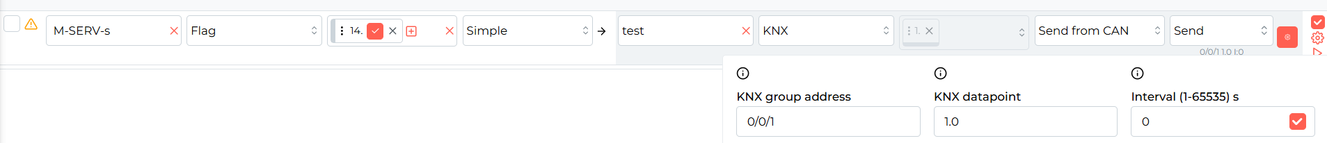
To transmit data from the Ampio system, create a condition, e.g. from a binary flag from any module, and select the M-CON-KNX-s module as the target. In the condition settings, specify the KNX group address, the data type and the interval, i.e. every how many seconds data are to be sent cyclically if the state of the flag does not change. An interval set to 0 results in data not being sent every period of time, but only on a change of state.
 Click to enlarge and open in a new tab.
*from January 2024, the Smart Home Configurator software is no longer being developed. It is recommended to use it only in substantiated instances.
Configuring parameters and single conversions is performed in the Ampio Smart Home configurator (version min. 5.0.0.6822). The first step is to launch the application, wait for the list of devices to load, select M-CON-KNX-s from the list and open Device parameters.
 Click to enlarge and open in a new tab.
Devices from the KNX bus will be shown in the CAN bus as virtual devices. Their address will be displayed in the 1100PPAA format, where PP stands for the address prefix, and AA stands for an editable part of the address. In the Basic tab you can change the mentioned prefix and edit the physical address that the M-CON-KNX-s bridge uses to send data into the KNX bus. Visible are also the PCB version, protocol and software version of the subprocessor.
 Click to enlarge and open in a new tab.
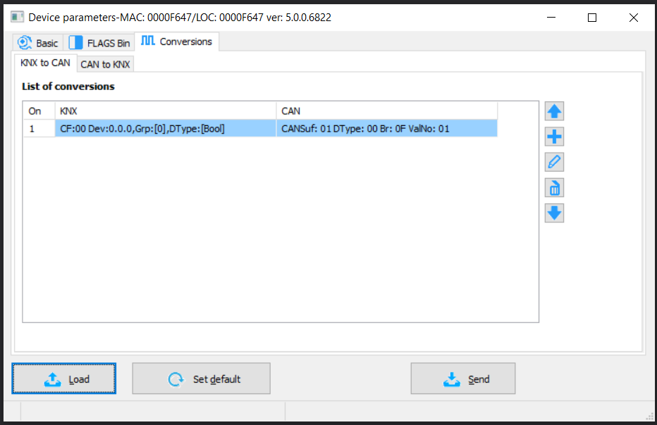
In the Conversions window, there are two tabs, in which you can configure information conversion between buses.
 Click to enlarge and open in a new tab.
Using the right buttons, you can add, edit, or remove conversions from the list. After adding a conversion, you will see a window with its settings.
 Click to enlarge and open in a new tab.
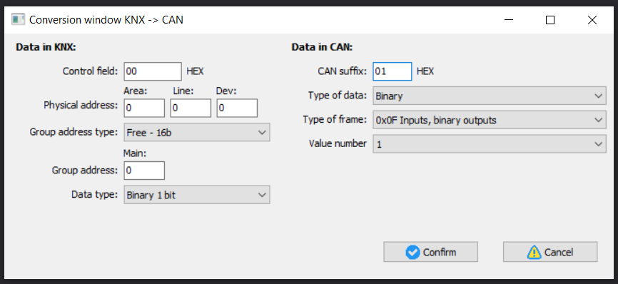
Control field should be left at default, addresses copied from the KNX project and the right Data type should be selected. Next, determine how data should be transmitted to the CAN bus. Change the editable part of the address (suffix) and configure the Data type, Information type and Value number (one device in the CAN bus can send e.g. 3 temperature values in one frame), and confirm. When you are done, remember to send the new lists to the device.
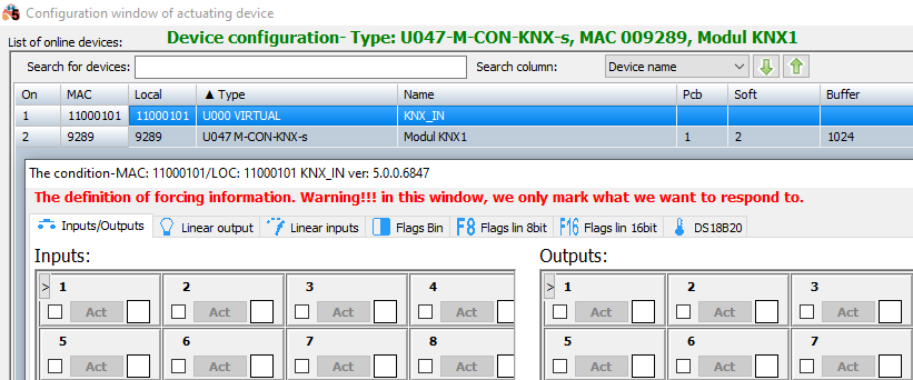
In order to create conditions for KNX devices, you must add a virtual device in the configurator (with an address in the following format: 1100PPAA, where PP is a prefix from Device parameters, ana AA is a suffix from particular translations; the exact address can also be viewed in the Network monitor). The process of adding such a device is described in the Virtual devices guide. Having added such a device, you can create conditions from the virtual device, which will transmit information from the KNX bus. To achieve this, enter the Device configurator of the target module, select the virtual device from the next list and click Add condition from device.
 Click to enlarge and open in a new tab.
If you want the virtual device to be visible on the list on the next launch of the configurator, save the project by going to the Project tab and click Save project. You will then open the saved project with the next launch of the application.
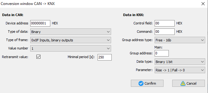
In the second tab, you can configure conversions from the CAN bus to the KNX bus.
 Click to enlarge and open in a new tab.
Add a new conversion, set its parameters, and add a full CAN Device address. Then choose what Data type, Information type and Value number you want to transmit. On the KNX side leave Control field and Command at default. Then select the address with which data will be sent to the bus, determine the Data type and Parameter if needed.
For binary inputs/outputs there is a possibility of configuring reactions to the signal slope (from subprocessor software no. 13). In accordance with descriptions, you can define reactions to an increasing slope and a decreasing slope. The reactions can be as follows: sending 1, sending 0, or no reaction (marked as -).
Some of the data types are sent from the CAN bus in multiple frames (selected in the Type of frame field). Because of that, if you want to e.g. select the temperature sensor no. 4 from an Ampio module, you must set the Type of data as Exact temperature, Type of frame as 0x07 2-byte temperature, and Value number as 1.
 Click to enlarge and open in a new tab.
From now on, data from the CAN bus will be visible in the KNX bus. If you would like to check how everything is working, you can use e.g. nie ETS application and the Diagnostics tab.
From the configurator version 5.0.0.7291, there is a possibility of regular transmission of data from the CAN to the KNX bus, even if values have not changed. For the function to work properly, the secondary processor must be of at least version 31 (info displayed in the Basic tab). Time that can be set for the module ranges from 10 to 250 seconds.
In order to add a condition from binary outputs in the CAN system, you should select “Binary” Data type, “0x0F Inputs, binary outputs” in the Type of data and add 24 to the output’s value (max. number of inputs). For example, for output no. 1, select type 0x0F, value number 25, and for output no. 2, select type 0x0F and value number 26, etc.