The installer kit comes with a number of different devices from the Ampio offer that allow a new installer to learn the Ampio system, its logic, and configuration. The kit also includes some Ampio gadgets that will not be discussed in this document. This guide will focus solely on explaining the first steps with the Ampio Installer Kit in order for a new installer to grasp the logic of the Ampio system and start implementing basic automation solutions.
The M-SERV-s unit is our flagship module packed with the most useful features for all your building automation needs. This module is mostly responsible for IP integration and internet connectivity, hosting the Ampio Designer programming and configuration interface, as well as handling the mobile application. The module also comes with Node-Red preinstalled and has a built-in MQTT broker, SIP server for video intercom handling and supports streaming with the use of the Airplay protocol.
Other than those networking features the M-SERV-s also sports some great standalone functionality, such as:
The M-DOT-M18 is our flagship touch panel, featuring 18 separate touch fields as input, a 1-Wire temperature sensor connection, a controllable buzzer and a scrollable, full-colour, 2” LCD screen. All touch fields have an RGB status LED and an RGBW LED backlight, both of which can be controlled using device parameters and logic. Also, the fields can have custom icons and labels engraved on the top glass part of the touch panel. The touch panel’s look can be customised at kreatorpaneli.ampio.pl.
The panel, because of its large size and LCD display, is uniquely equipped with some distinctive features, e.g.:
The M-SENS-LITE is a basic environmental parameter sensor, which connects directly to the CAN bus and reports the values of multiple parameters to the system.
The module measures:
The M-IN-2p is a miniature input module meant to be mounted in electrical junction boxes and behind switches. The module connects directly to the CAN bus and features 2 ground detecting inputs, a 1-Wire bus connection for digital temperature sensors and a brightness sensor for detecting whether the module has been taken out of its mounting place.
The S-LED-U is our own LED light driver that works with the One Wire Ampio lighting bus. This voltage driver board acts as a node on the OWA bus, allowing for individual dimming control of the connected voltage-controlled LED light.
The DALLAS DS18B20 temperature sensor is a simple digital temperature sensor, which connects to the 1-Wire bus and reports its current temperature to it.
To fully understand how to use our Ampio Designer configuration software we highly recommend reading the Ampio Designer guide, but for the purposes of this document a quick overview of device configuration and logic will be provided.
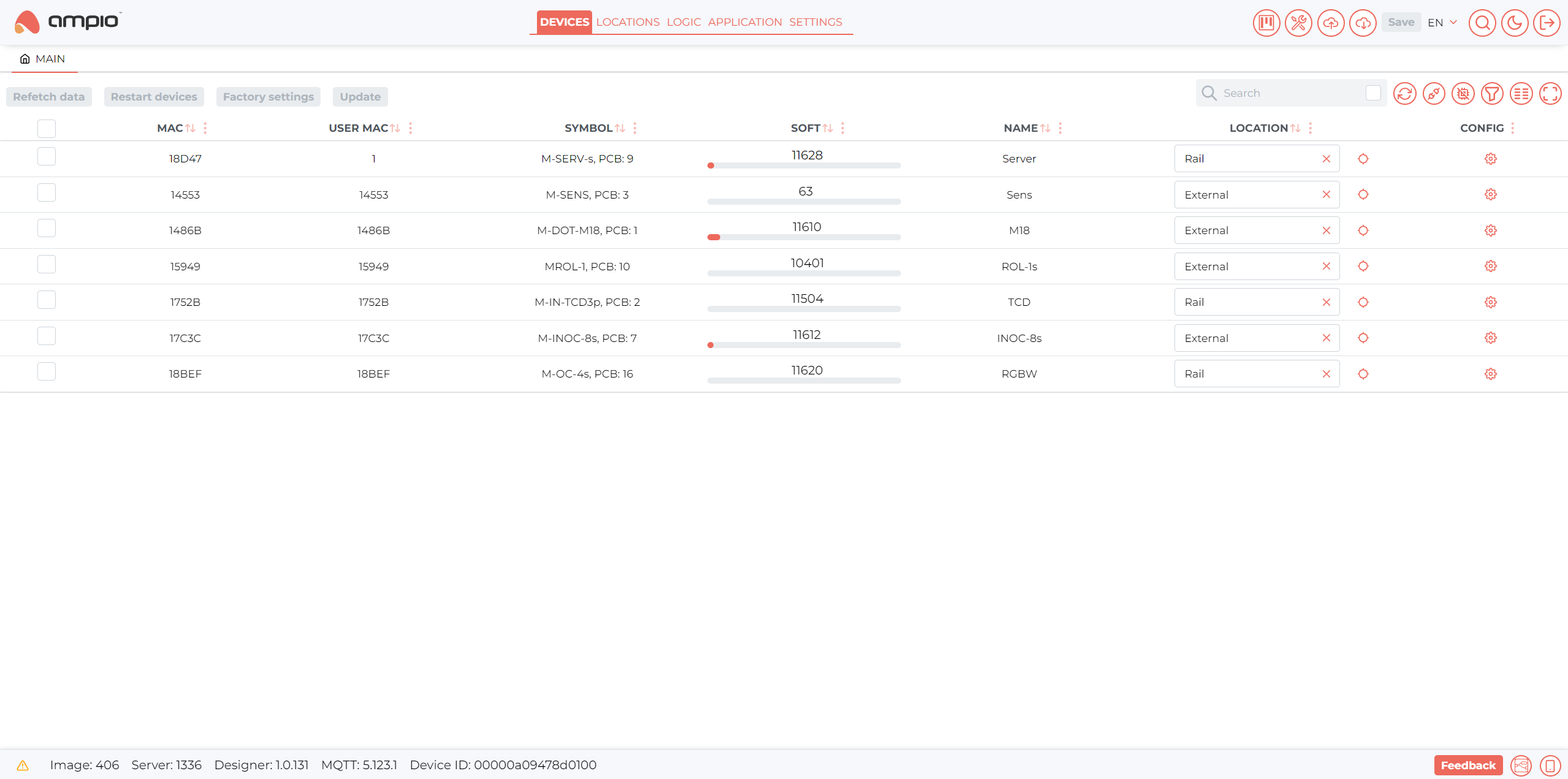
In the Devices tab all the devices connected to the same CAN network as the M-SERV will be displayed together with some important information relating to them:
 Click to enlarge and open in a new tab.
The information is displayed in the following columns:
Inside the configuration menu more detailed information about the individual device can be found together with many configuration options.
The most important menus can be found under the Functionalities and Parameters tabs.
 Click to enlarge and open in a new tab.
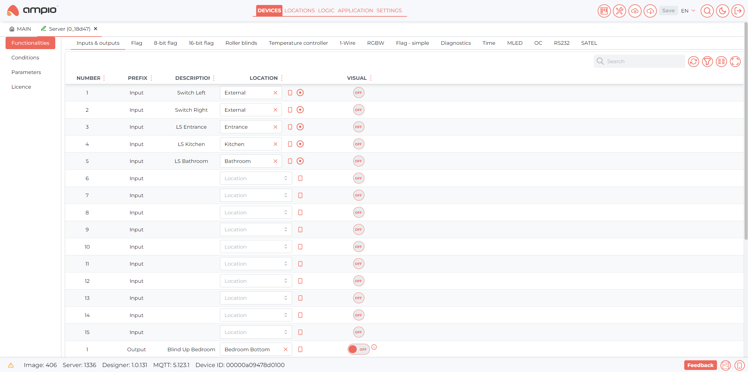
In the Functionalities tab you can see an overview of all the functions available in the device.
The different inputs, outputs, flags and special functions like temperature controllers, RGBW drivers, roller blind controllers, etc. can all be named and assigned a location.
You can also see real time visual feedback of the current state of the function as well as manually control them for debugging purposes. After changing anything in the device’s functionalities the “Save” button in the top right corner of the interface will light up red, click on it to save your changes.
 Click to enlarge and open in a new tab.
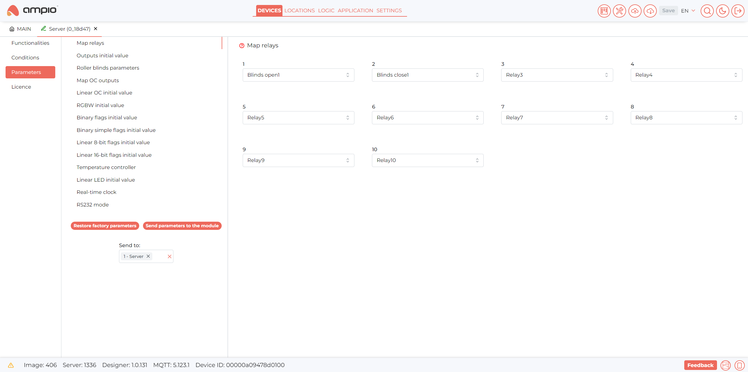
In the Parameters tab you can adjust the device’s parameters so that it can work exactly as you want it to work. Outputs can be mapped, initial values set, and specific function parameters changed.
After changing any devices parameters click the “Send parameters to the module” below the parameter list to save your changes.
In the Logic tab all your logic conditions and functions will be created, examples of such functions will be shown in the sections below.
In this section the basic interface elements need to create those functions and conditions will be presented.
 Click to enlarge and open in a new tab.
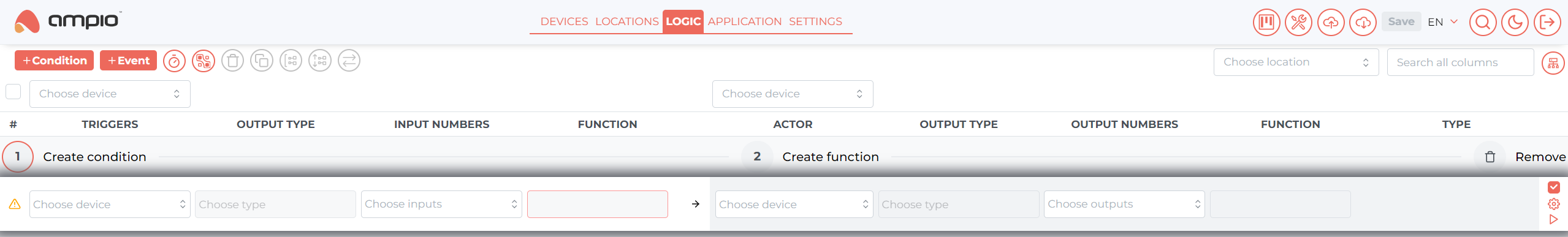
To start creating a condition press the “+ Condition” button in the top right.
The “+ Event” button works in a similar way to the “+ Condition” button, except that it creates an action in response to an event broadcast, which will be discussed further in this guide.
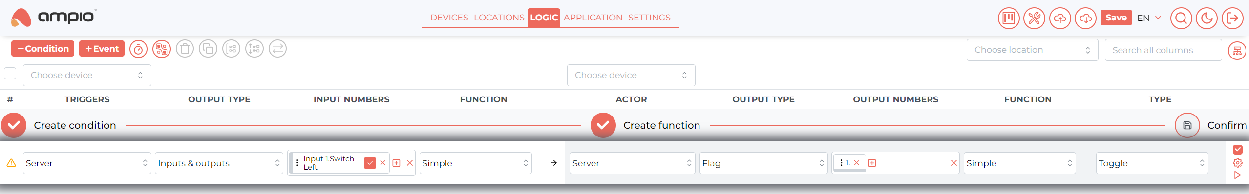
After pressing the button, a condition creation field will appear. It is split in 2 parts:
The condition – in here you will create a condition, which will call the created function when evaluated in the specified way. To configure it specify the following things in the presented fields:
The function – what action should be taken upon condition evaluation. To configure it specify the following things in the presented fields:
When the condition is completed correctly ticks (✓) will appear above the specific parts of the condition and the “Remove” button will change into a “Confirm” button:
 Click to enlarge and open in a new tab.
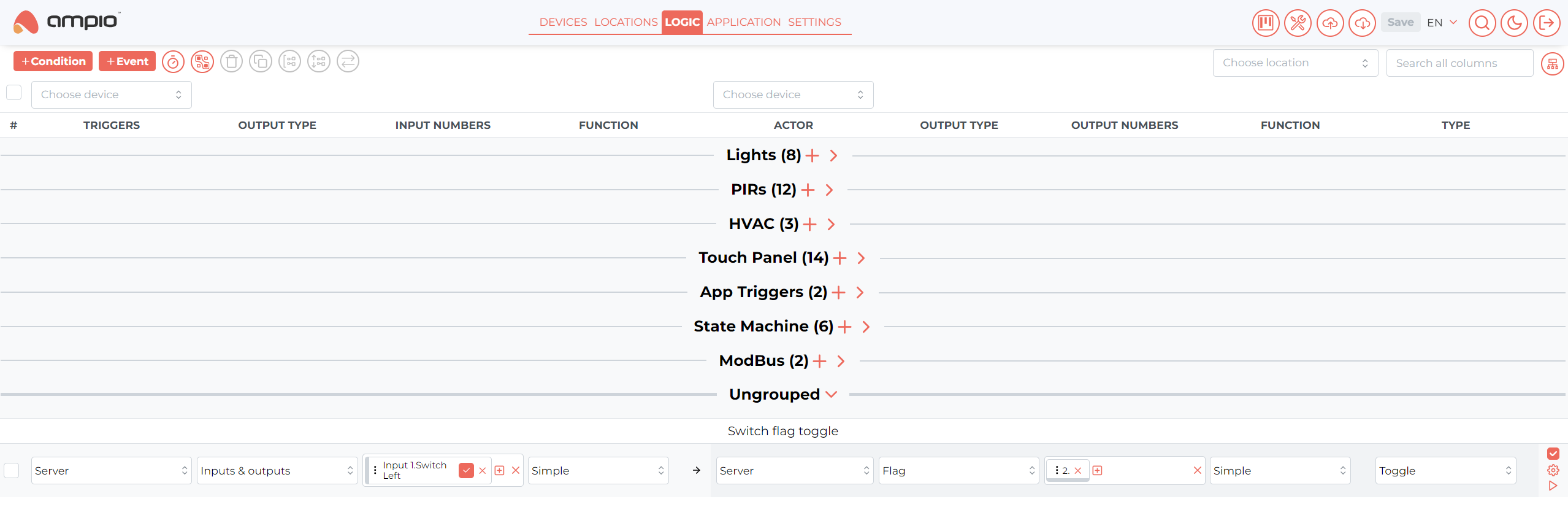
Upon confirming a new condition, a couple of useful user interface elements will be available to further check the functionality of the condition:
 Click to enlarge and open in a new tab.
On the left side of the added condition, 2 icons will appear:
On the right side of the conditions, 3 buttons are located:
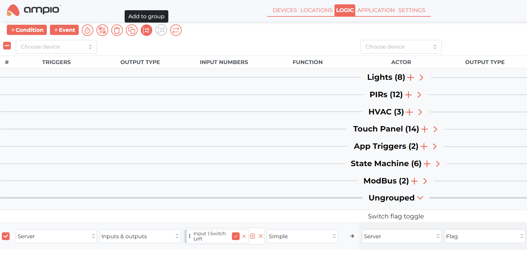
Multiple conditions can also be selected with the checkbox on the left and added to a group, using one of the buttons in the top left corner, for easier condition sorting and management.
 Click to enlarge and open in a new tab.
 Click to enlarge and open in a new tab.
We highly recommend creating some conditions and experimenting with different options on your own, but in the following sections we will present a few examples of how to achieve basic building automation functions.
The simplest way to control a light.
Connect the relay to a light of your choice (incandescent, LED, etc.) and wire up an input switch to either one of the inputs of the M-SERV-s or the M-IN-2p.
Create a simple condition in the Ampio Designer’s Logic tab:
 Click to enlarge and open in a new tab.
Now, every time the wall switch’s button is pressed, the light will switch ON/OFF.
Connect the relay to a light of your choice (incandescent, LED, etc.) and select a touch field of your choice (if one of the 4 corner fields around the LCD display is selected an icon with status notification can be configured).
Create a simple condition in the Ampio Designer’s Logic tab:
 Click to enlarge and open in a new tab.
Now, every time the selected touch field is tapped, the light will switch ON/OFF.
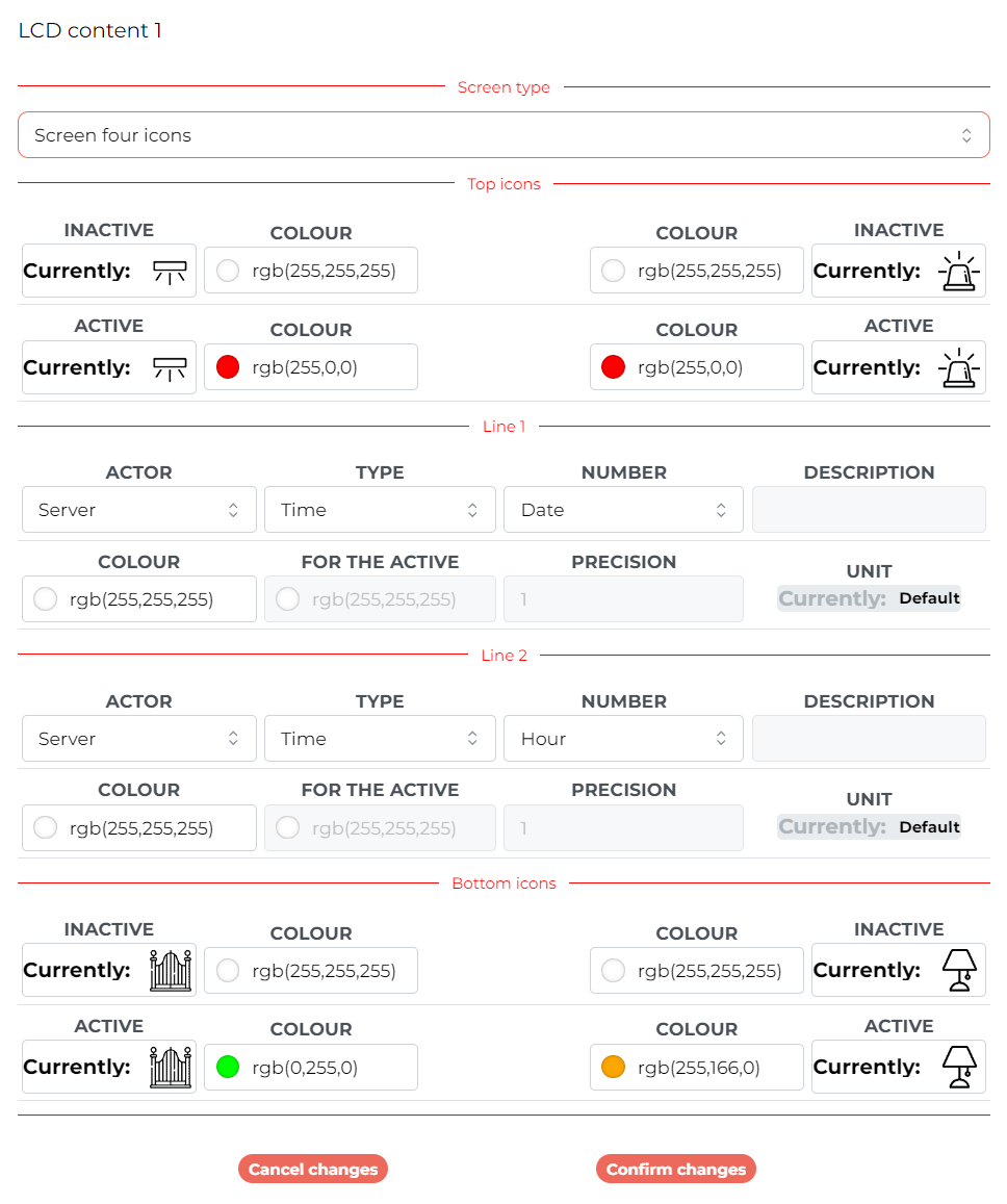
First, in the M-DOT-M18 configuration menu, select the Parameter -> LCD tab, select the screen you want to configure, and select the “Screen four icons” screen type and set up the desired icons.
An example of a 4-icon screen configuration with the date and time displayed is presented below:
 Click to enlarge and open in a new tab.
To change the colour of an icon in response to the state of the light, a simple condition can be made to copy the status of the output to the status of the icon:
 Click to enlarge and open in a new tab.
Now, the icon should change the colour when the light is ON.
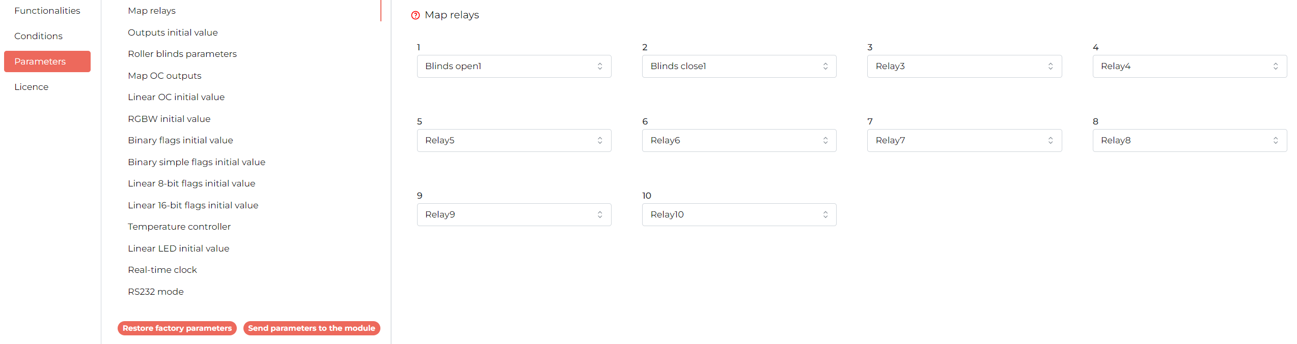
In most of Ampio’s modules which are equipped with relay outputs there is a “roller blind controller” built in. To use this feature relays, which operate the blind’s motor, need to be mapped as Blind Open and Blind Close, this can be done in device parameters:
 Click to enlarge and open in a new tab.
Here the relays 1 and 2 of the M-SERV-s are mapped to opening and closing a blind under the blind controller number 1.
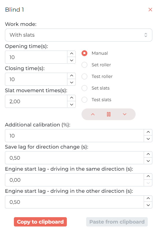
Next, the actual controller parameters need to be configured, to do that move to the Roller blinds parameters tab. The roller blind control is time-based, meaning all parameters relating to the blind movement are in seconds of motion:
 Click to enlarge and open in a new tab.
A couple of important parameters can be configured in this menu:
Here, standard blinds are configured, which open and close in 10 seconds, stop for 0.5 seconds when changing directions and perform a 10% calibration movement.
Finally let us create some logic to control the blind, there are a couple of ways to do that.
One-button approach utilises only a single input, which can be a little bit restrictive.
Any input function can be used (ex. M-SERV-s or M-IN-2p physical inputs), here the M-DOT-M18 touch panel’s input will be used.
With a single input a blind can be set at a position or be controlled in a start/stop/start manner, which will be shown here:
 Click to enlarge and open in a new tab.
Now, when an input is detected, the blind will start moving, when detected again, the blind will stop, and when detected again, the blind will start moving in the other direction.
With two inputs a much greater level of control can be achieved.
Any input function can be used (ex. M-SERV-s or M-IN-2p physical inputs), here the M-DOT-M18 touch panel’s input will be used.
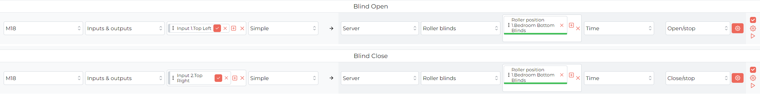
With two inputs the blind position can be incremented and decremented by a certain step or continuously controlled, two conditions need to be created, one for each input:
 Click to enlarge and open in a new tab.
In the example above when the top-left touch field is touched the blind will start opening or when the top-right field is touched the blind will start closing. If any of the fields is touched while the blind is in motion it will stop.
The One Wire Ampio lighting bus is a very convenient and cost-effective solution for your lighting needs, allowing you to connect up to 16 individually addressable lighting nodes with just 3 wires, one for supply voltage, one for data and one for common ground connection.
Most of the features presented for One Wire Ampio lighting and the M-LED lighting driver are also applicable to Open Collector (OC) outputs.
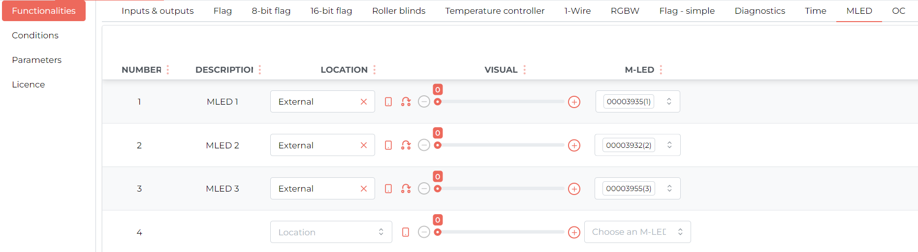
Once connected the recognised lights should be available in the M-LED driver’s Functionalities tab in the device’s configuration. For this demonstration, the M-LED driver of the M-SERV-s module will be used:
 Click to enlarge and open in a new tab.
Here 3 lighting nodes are connected, their addresses are assigned to numbers 1, 2 and 3, respectively. Multiple addresses can be assigned to one number for group control.
Since only one MLED driver board is provided in this kit further instruction will be considering only single light functionalities.
All lights connected to the bus have dimming capability, so they can not only be turned ON and OFF, but also their brightness can be easily adjusted.
Dimming can be achieved in many ways, for thw purpose of this document a simple binary input, like a switch, button, touch panel field, etc. will be used. In the examples to follow, momentary switches connected to the inputs of the M-SERV-s will be used.
A single input is very convenient for everyday lighting needs and with some logic both toggling the light and dimming with the same button.
A simple light toggle:
 Click to enlarge and open in a new tab.
The max brightness was adjusted below the device maximum. Also, Step can be adjusted to control the brightness ramp up and down speed when switching the light.
Now when the button is pressed the light will toggle ON and OFF.
Let us add the dimming functionality, this can be done by changing the output function to Auto inc/dec (automatic increment / decrement):
 Click to enlarge and open in a new tab.
Now when the button is held, the light will slowly increase in brightness until the button is released or the light reaches the configured max brightness, then, when the button is pushed again the light will decrease in brightness until the button is released or it reaches the configured minimum brightness.
The Step and Interval parameters can be adjusted to control the brightness ramp up and down speed.
Since the dimming works when the button is held, to avoid condition interference between the functions let’s change the toggle’s input function to Maximum impulse time and *Duration measurement *for the dimmer, this will stop the functions from running together, toggle will work for short presses and dimmer will trigger only after a certain time threshold (here the threshold is 0.5s for both input functions):
 Click to enlarge and open in a new tab.
With the Auto inc/dec function sometimes it can be hard to know whether the light will get brighter or dimmer when the button is pressed. With two buttons the brightness ramp up and down functions can be split between them for finer control of lights, whose brightness needs to be accurately set.
2 conditions need to be created, one for incrementing and one for decrementing the brightness value:
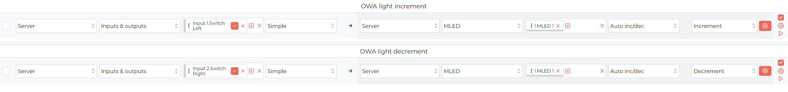 Click to enlarge and open in a new tab.
Now Switch Left (input 1) will increase the light’s brightness and Switch Right (input 2) will decrease it.
To allow light toggling without time restrictions like the ones used with the single button control style the AND function will be used to only trigger the toggle when both buttons are pressed at the same time.
To avoid condition collisions an interlock will be used on the dimmers to make them work only when one of the buttons is pressed, this will also utilise the AND function, but with one of the switches’ inputs inverted to prevent the function from working when both buttons are pressed:
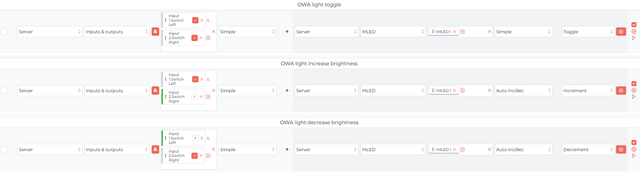 Click to enlarge and open in a new tab.
Now when only Switch Left is held the light will get brighter, when only the Switch Right is held the light will get dimmer and when both are pressed at the same time the light will toggle ON and OFF.
A temperature controller is the universal solution for keeping your rooms at exactly the temperature you want.
The M-SERV devices have a built-in temperature controller which can handle from 1 to 32 individual heating zones (depending on the license purchased). Together with the fact that most of our devices support an input for 1-Wire temperature sensors, setting up temperature control with our temperature controller is very convenient.
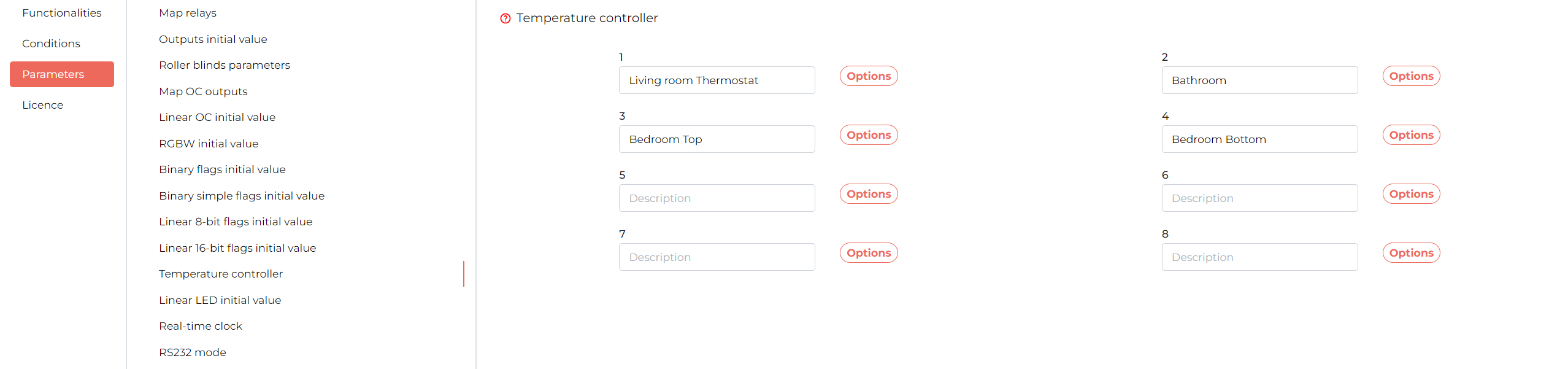
To configure how the temperature controller should behave, enter the M-SERV’s device configuration and in Parameters -> Temperature controller:
 Click to enlarge and open in a new tab.
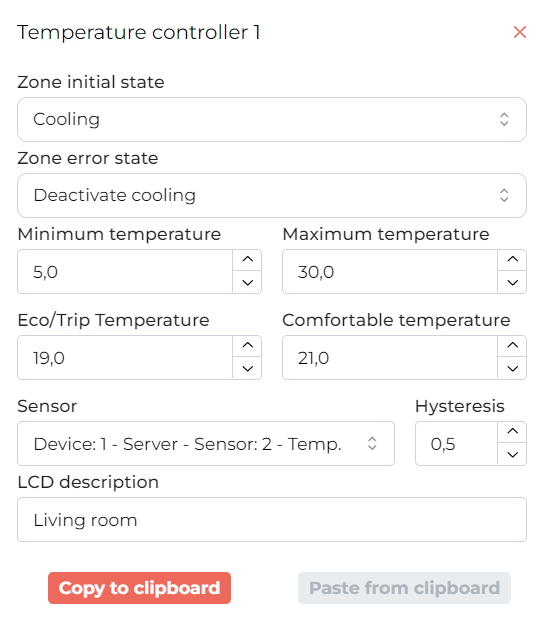
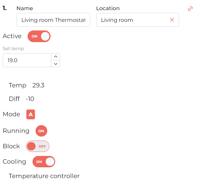
Here select one of the available zones for configuration, for the purpose of this example the Living room Thermostat will be configured:
 Click to enlarge and open in a new tab.
A couple of parameters can be configured:
To see the current state of the temperature controller can be seen in the Functionalities tab:
 Click to enlarge and open in a new tab.
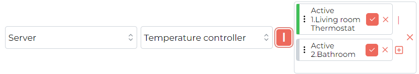
To utilise the temperature controller, logical conditions need to be created using the different parameters that the temperature controller provides for each individual zone.
Here is a list of the parameters that the controller makes available in conditions:
 Click to enlarge and open in a new tab.
 Click to enlarge and open in a new tab.
Using those conditions integrated heaters, radiators and AC units can be controlled.
The states and parameters of the temperature controller can also be set and adjusted using logic, we recommend looking through the different options available and testing them out.
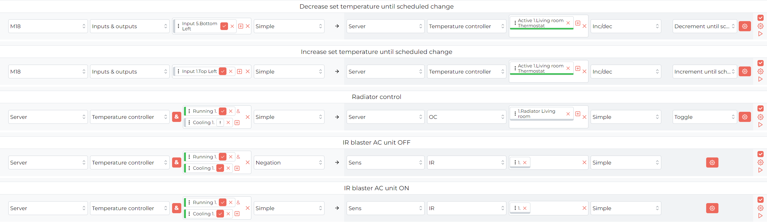
With a few conditions a simple temperature control system can be set up for a room. When combined with one of our M-DOT series touch panels as a display and for control purposes, a great all-in-one temperature control package can be created:
 Click to enlarge and open in a new tab.
In this example the touch panel with the temperature controller display is used to adjust the set temperature.
When the zone is running and not in cooling mode the radiator will be ON.
When the zone is running and in cooling mode the Simple input function sends an IR code from the M-SENS unit to turn ON the AC on the *rising edge *(when the condition is evaluated true) and the Negation input function sends an IR code from the M-SENS unit to turn OFF the AC on the falling edge (when the condition is evaluated false).
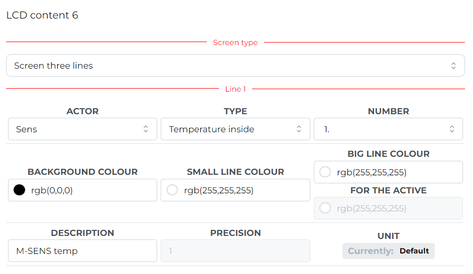
The M-SENS-LITE reports many useful parameters, which can be displayed to the user on a touch panel’s LCD display.
The values can be selected in the M-DOT-M18 device parameters under the LCD tab.
Select the screen you want to use and the screen type of “Screen four icons” if used with additional controls in mind or “Screen three lines” for more space to display data.
Here is an example of displaying the temperature measurement from the M-SENS-LITE module on the panel’s LCD screen using “Screen three lines”:
 Click to enlarge and open in a new tab.
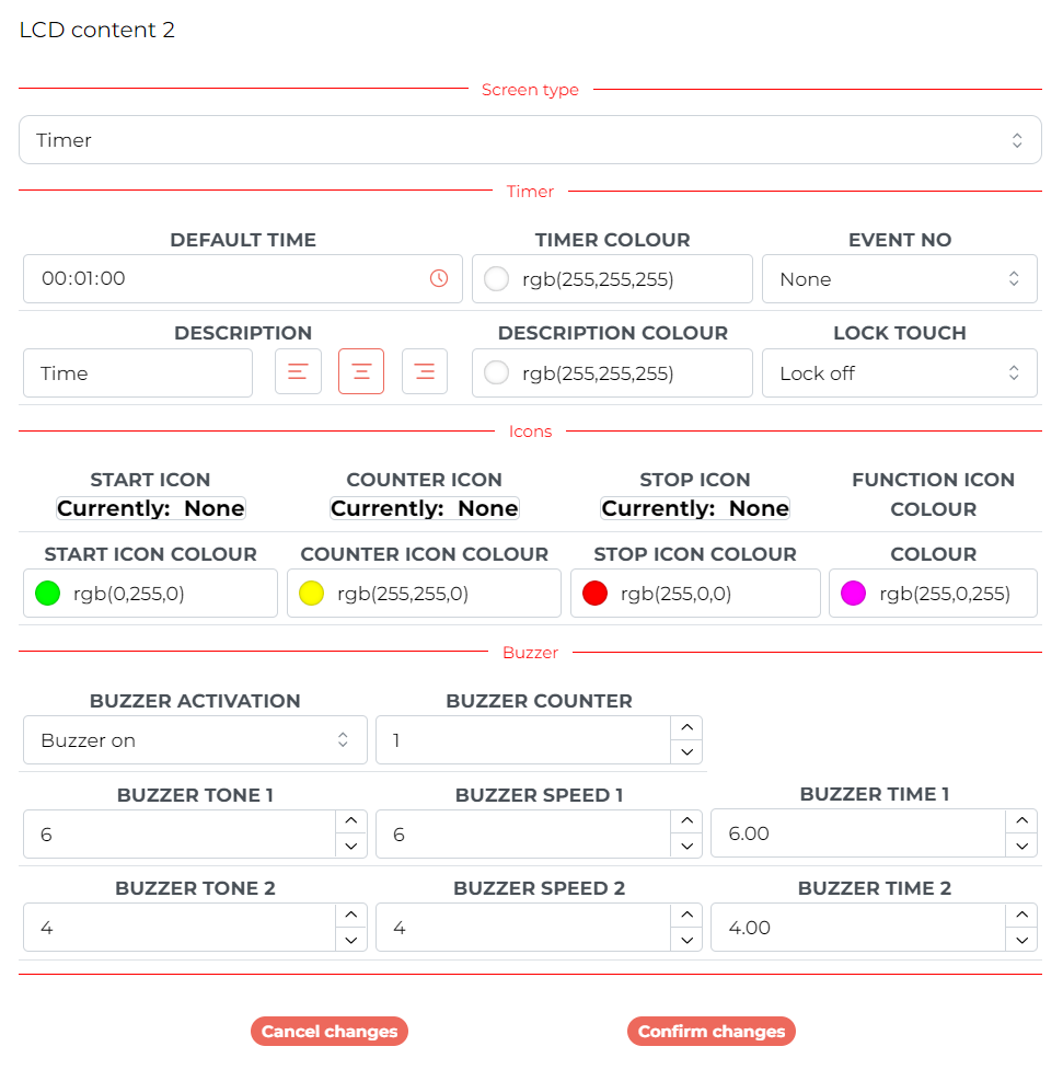
The timer screen is a particularly useful and simple tool available within the touch panel.
This screen allows the user to start an adjustable timer, which will trigger the panel’s buzzer, or an event, when it runs out.
Events are signals broadcast to the entire network, to which other devices can respond, they can be defined under Resources in the Settings tab.
The timer’s user interface is quite simple:
To add a timer screen, go to the M-DOT-M18 configuration menu, select the Parameter -> LCD tab, select the screen you want and select the ”Timer” screen type. There are a couple of parameters to configure:
 Click to enlarge and open in a new tab.
After configuring the timer how you want confirm changes and send parameters to the module. Now the timer will be available on one of the touch panel’s screens.
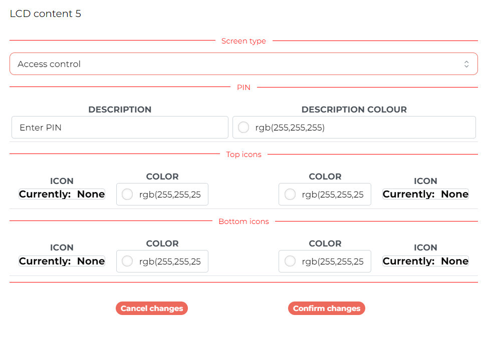
The M-DOT-M18 touch panel has the unique ability to broadcast events upon entering a predefined PIN code.
As mentioned in the previous section, events are signals broadcast to the entire network, to which other devices can respond. For the purpose of this example, an event “PIN 1” was created.
Click to enlarge and open in a new tab.
Next, in the M-DOT-M18 configuration menu, select the Parameter -> LCD tab, select the screen you want and select the ”Access control” screen type, type in the ”Description” field a message you want to display above the PIN input field.
In addition, icons can be selected in a similar fashion to the “Screen four icons”, this will be omitted here.
 Click to enlarge and open in a new tab.
Next, in the Access control tab add a new PIN code and select the event to broadcast upon entering the PIN code.
 Click to enlarge and open in a new tab.
Finally, a piece of logic is needed to use the event call, here a relay will be switched ON for 2 seconds upon entering the PIN code:
 Click to enlarge and open in a new tab.
Now every time a PIN of 1234 is entered into the ”Access control” screen, the relay will turn ON for 2 seconds.
The action called does not necessarily have to be a relay trip and can trigger any action you programme in the Logic tab.