One of the integration possibilities of the Ampio system is communication with the Satel Integra alarm system. It is feasible to connect a number of Integra-type control panels, for example:
In order to integrate the Integra system with Ampio, you will need a complete control panel, the Satel’s INT-RS interface, and the Ampio’s M-CON-232-s module (or appropriately configured M-SERV-s).
For the M-CON-232-s device to enable the described functionality, it has to have the correct software installed according to the RS-232 integration module document. The software chosen for the purpose of this guide is 2401, so the file that needs to be installed is called: ampio_T25_P6_S2401.amp. A guide describing the method of installing updates is the following: Manual updates.
In order to connect the M-CON-232-s device to the INT-RS interface, you first need to assemble a wire compatible with the RS232 standard, as depicted in the figure below.
 Click to enlarge and open in a new tab.
In the newest version of the INT-RS interface, the wire connection is verified - the red wire shown in the figure below needs to be connected to the socket. This means that the connectors 1, 4, and 6 must be connected. If the connection is not prepared, the control panel will return a “DSR error”. The DSR signal verification can also be deactivated in the control panel, according to the Satel Integra manual (Service mode->Structure->Equipment->Manipulators->Settings->INT-RS->DSR control). Once the equipment part is ready, you can proceed to the basic connection configuration.
The first step is to configure the INT-RS correctly. This can be achieved by the right setup of switches on the board. It is important to set the interface address to a different one from the one assigned to the manipulators connected to the control panel. Set the address up according to the interface’s manual (switches 1-3). Then, configure the interface to work with other systems (switches 4-10: 5 set to ON, the rest set to OFF). The figure below illustrates the described settings.
 Click to enlarge and open in a new tab.
Then, search for the configured interface in the control panel, following the manual, in a similar way to the manipulators (Service mode-> Structure->Equipment->Identification->Manipul. ID). Connect the INT-RS with the M-CON-232-s and the previously prepared wire. From now on, you will be able to communicate with the Satel Integra alarm.
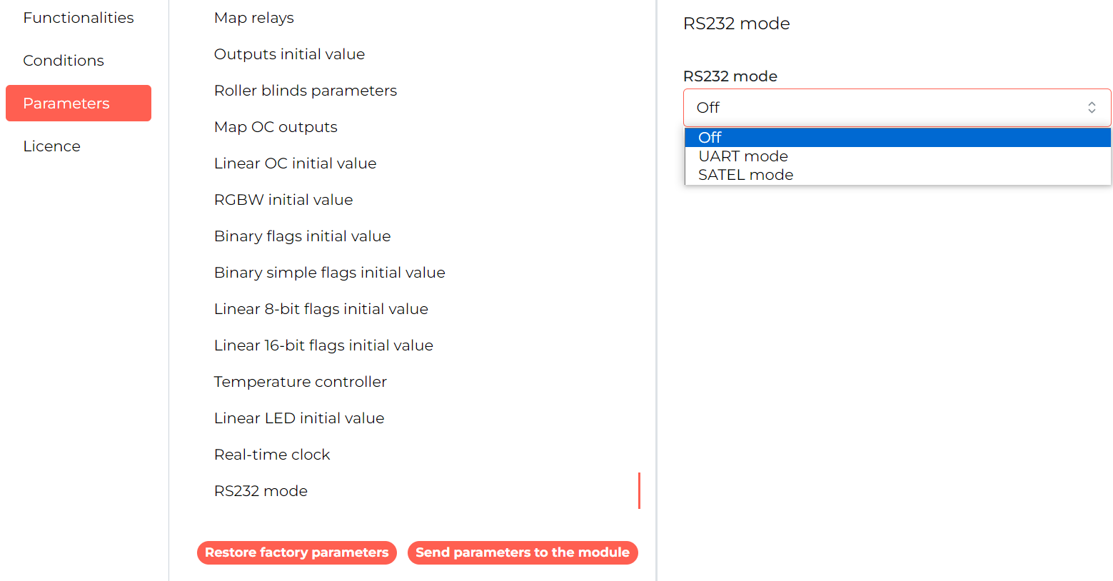
To start configuring the integration, select the M-SERV-s or M-CON-232-s module on the Ampio Designer main screen and enter its settings (gear icon). Then select the Parameters tab. The following screenshot shows the RS232 mode setting in the M-SERV-s module.
 Click to enlarge and open in a new tab.
In order to configure the support of the Satel integration in the M-CON-232-s module, the corresponding software must be uploaded, as described in the chapter Installing the right software.
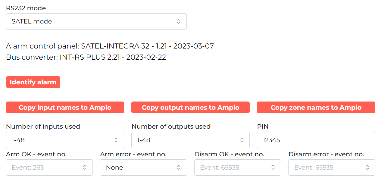
In the next step, select the button Alarm identification. The alarm will be identified anew with each new Ampio Designer session in order to test the communication. Thanks to the automatic identification, it is possible to find out with which control panel model the integration is performed and what software is in it.
 Click to enlarge and open in a new tab.
In the same window, it is possible to enter a PIN into the memory or copy the names of zones, outputs or areas from the control panel to Ampio. In addition, you can also select which event will be generated in the Ampio system after a corresponding alarm event.
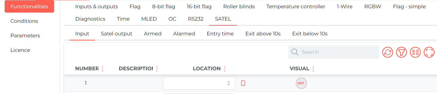
To check the statuses of inputs, outputs or zones, select Functionality, then SATEL and the relevant sub-tab e.g. Input.
 Click to enlarge and open in a new tab.
Conditions can be created from, among other things, the status of an output in the control panel or, for example, the arming status of a given zone.
 Click to enlarge and open in a new tab.
On the other hand, you can control, among other things, the status of an output, a zone or the entry of a PIN by, for example, entering consecutive digits.
 Click to enlarge and open in a new tab.
*from January 2024, the Smart Home Configurator software is no longer being developed. It is recommended to use it only in substantiated instances.
The first thing to do is to identify the control panel and the INT-RS interface type. In order to do that, open the M-CON-232-s' device parameters.
 Click to enlarge and open in a new tab.
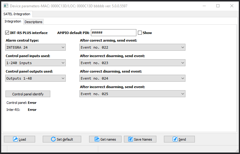
In the Integration tab, set all the data associated with the control panel’s operation. It is possible to carry out the identification of the INT-RS communication interface and the Integra control panel itself. This can be achieved by clicking on the Identify control panel. The software will download the necessary data and will display it in the Control panel and Inter-RS columns. Once the identification is performed, some parameters can be set automatically. What is crucial to remember is selecting the number of used inputs and outputs. The used control panel inputs/outputs parameters were created to enable the functionality of reducing traffic on the CAN bus. Here, you can choose the scope of inputs/outputs within the ranges of: 1-48, 1-96, 1-144, 1-240, 1-256. If the integration requires, for example, only the first 40 inputs and 80 first outputs, we recommend selecting the smaller ranges.
If the set range is too small, you will not receive information from some inputs and outputs.
Some of the functionalities used in the integration require providing the password of a user with appropriate permissions. One of the options here, is supplying the password by creating functions that can be realised by a numeric keypad, when entering a PIN code can perform a specific function.
There is also an option of sending commands without providing the PIN code every time. In order for the functions to work properly, you have to create a user in the control panel with sufficient permissions and enter the user’s password in the parameters. The password will be used to control outputs, and to arm and disarm certain zones. After each change in the Device parameters settings, click on the Send button.
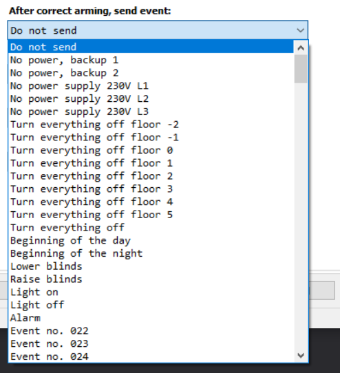
The next functionality is sending any defined event through the M-CON-232-s. There are four circumstances under which events are being sent. A part of the list is shown below.
 Click to enlarge and open in a new tab.
For each of the circumstances, you can select a different event number. Events are then sent when a given situation is triggered by the Ampio system. So, for example, when you arm, or disarm the alarm in the Ampio system, an appropriate event will be generated.
If the same action is triggered in the control panel’s manipulator, the event will not be sent.
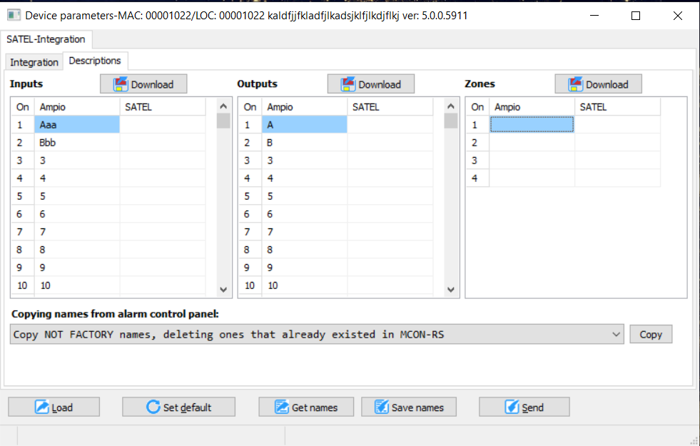
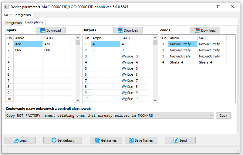
There is an option to download descriptions of inputs, outputs and zones that are stored in the control panel in the Descriptions tab. It makes the whole process of integrating with the alarm system much quicker. Because the communication with the control panel is slow, there are three buttons, each of which triggers the function of downloading a specific type of descriptions.
 Click to enlarge and open in a new tab.
This facilitates downloading only the descriptions that are actually needed. The window contains three lists, one for each description group. In each table, there are two columns: Ampio and Satel. As soon as the names from the control panel have been imported, they will be shown in the Satel column. This column is temporary and it is not stored in the M-CON-232-s device. The Ampio column, on the other hand, is stored, so for the names to be saved, they have to be moved to this column. It is possible to edit the contents of the column manually, or to move them automatically from the Satel column to the Ampio column by clicking Copy.
It is plausible that M-CON-232-s' storage capacity will not be able to contain all descriptions, so the copy option was created in such a way that it ignores any descriptions provided by the manufacturer. You can decide between different copying options that are available in the field located right next to the Copy
Below, you can see the result of copying zone names. If the names do not copy after a couple of seconds, click Save names and then Get names.
 Click to enlarge and open in a new tab.
If input names do not copy over, you have to change their type in the Satel control panel’s settings.
Such configured parameters must be sent to the device. The operation is conducted in exactly the same fashion as it is for the parameters of all other devices from the Ampio family, which is by clicking Send located in the bottom right corner of the parameters window.
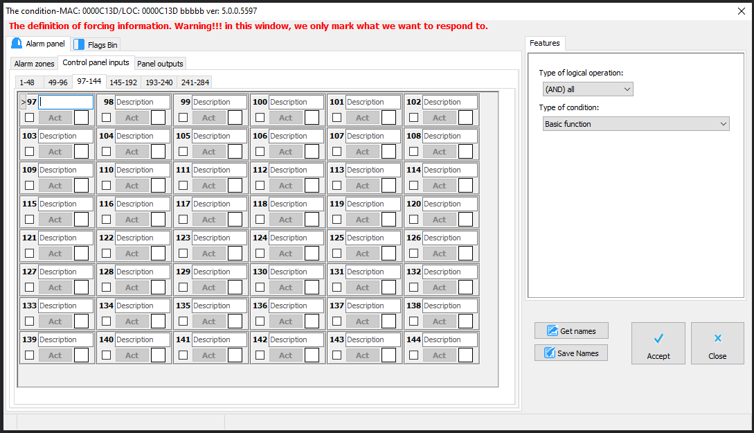
The creation of conditions is similar to the rest of Ampio devices. Select the inputs, choose the expected state and add a condition analysis function. It is crucial to remember that only the active tab takes part in the creation of a condition. For example, in the figure below, it means that only inputs 97-144 can be selected for the specified condition.
 Click to enlarge and open in a new tab.
In order to be able to use inputs from different tabs simultaneously, you will have to copy them over to flags and base the creation of the desired condition on flags. This window also serves as a device monitor, displaying the actions undertaken by inputs.
The rule for creating conditions from the control panel’s outputs is exactly the same as for inputs. The tab also serves as a monitor, but even though it is an output monitor, the outputs cannot be controlled. It is caused by the uniqueness of the alarm unit, which does not allow controlling any kinds of outputs. Control is only possible for stable MONO and BI outputs. More information regarding outputs can be found in the section dedicated to managing outputs.
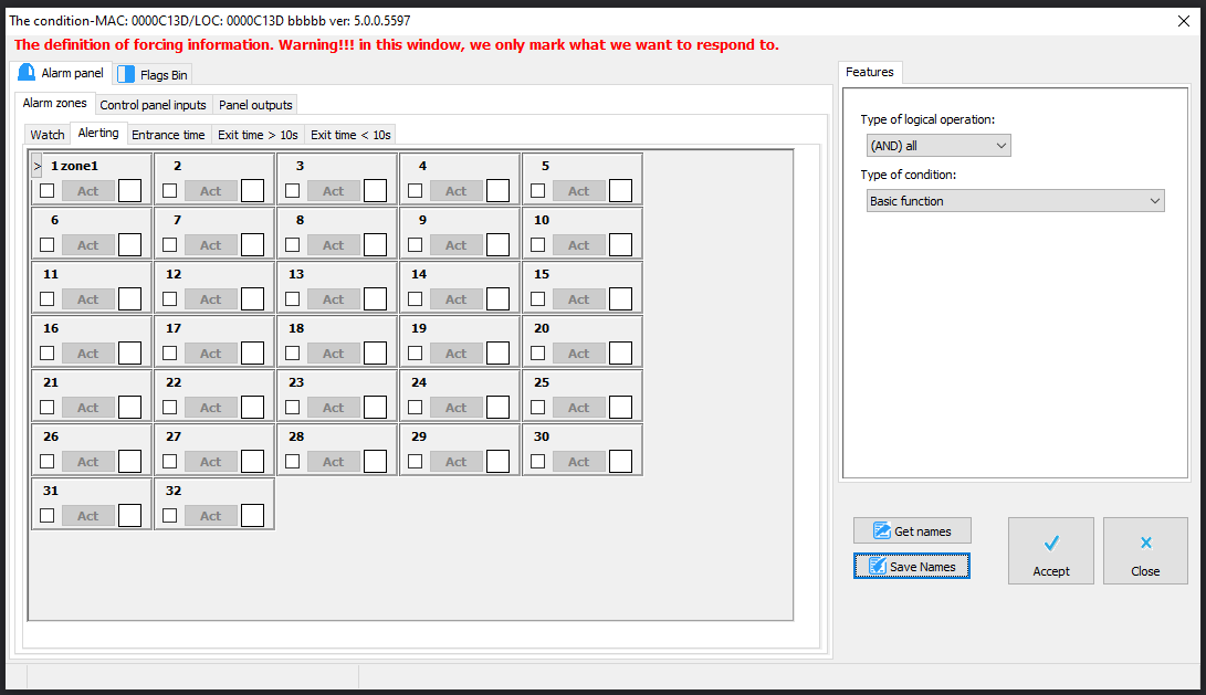
The rule for creating conditions from zones is exactly the same as for inputs, outputs and flags. There is one additional option. Conditions can be created from a zone’s idle state, or the state of alarming zones. Here, the condition is also created only from one of the selected options.
 Click to enlarge and open in a new tab.
Configuring conditions from flags is identical to the rules that apply to inputs, outputs and the rest of Ampio devices.
The first tab’s function during the creation of a condition for M-CON-232-s in Satel version is shown below.
 Click to enlarge and open in a new tab.
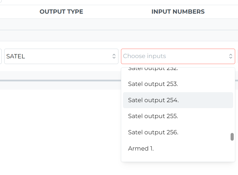
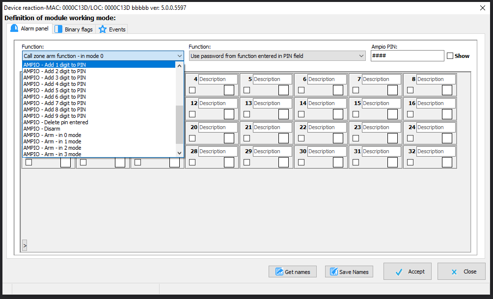
The tab, identically to the conditions editing tab, serves as a monitor for zones and control panel’s outputs. Below are the examples of the available functions accessible through the drop-down list on the left:
It is possible to configure an Ampio touch panel in such a way that it becomes a numeric keypad for the alarm’s central panel. In order to do that, select the touch panel’s output and add a function, for example, AMPIO - Add 1 digit to PIN.
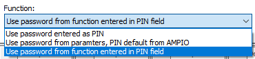
Controlling functions require a user password and this is where the PIN set in the parameters comes in handy. There are two options for entering the PIN. You can choose one by selecting the right option from a drop-down list shown below.
 Click to enlarge and open in a new tab.
In the first option Use password entered as PIN, the PIN is not defined in the parameters, but is generated on the basis of, e.g. the numeric keypad on the touch panel. The next option Use password from parameters, PIN default for AMPIO will lead to using the password entered in the M-CON-232-s device parameters, which was described earlier in this document. The last option, Use password from function entered in PIN field makes it possible to set a different password for each function. After selecting this option, another field will be displayed, where you will supply a PIN code used in the current function, as shown below.
 Click to enlarge and open in a new tab.
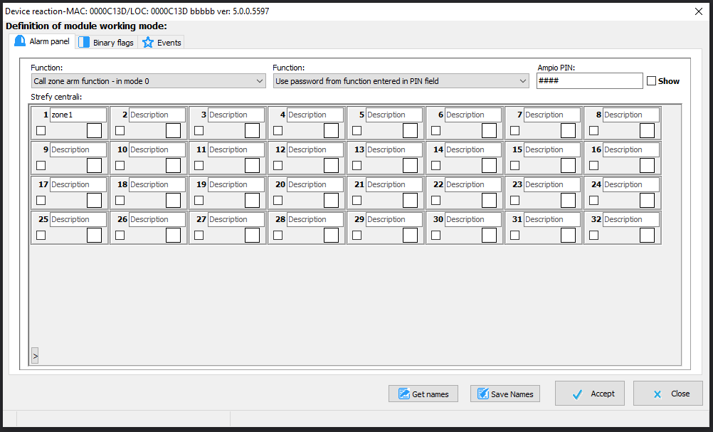
The PIN field is where you type the code and the Show tick box allows you to see the code typed in, similarly to the parameters window.
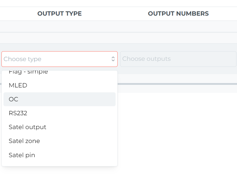
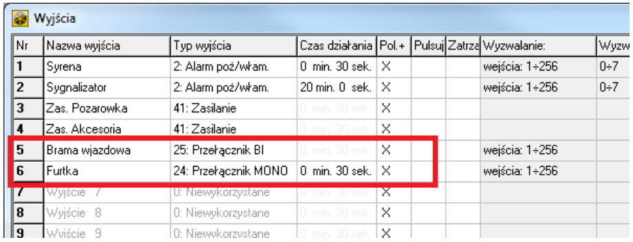
The first three positions are applicable to operations performed on the control panel’s outputs. An output can be switched on and off, or its state can be changed. The control panel allows one to control only a certain type of outputs, namely, BI switches and MONO switches. Therefore, in order for the output functions to work, it is important to configure the control panel’s outputs correctly. You can find sample settings of two outputs used in the Ampio system in the Satel’s DLOADX programme below.
 Click to enlarge and open in a new tab.
BI (bistable) outputs work like a light switch, or a relay output for Ampio devices. You can change their state, switch them on and off. The state of an output will only change with the next operation executed by the control panel, or the Ampio system. Mono (monostable) outputs can be set up, but it will be deactivated after the time described as operating time has passed, which means that it works on impulses, like a bell button. When you select the right controls, a full list of outputs will appear under the list of choices. On the list of outputs, tick the ones that you want to react to a given function. It is presented in the figure at the beginning of this section.
The other positions on the list of functions are related to controlling zones. There is an option of arming zones in different modes. You can also force arming of the alarm by using the trigger function in different modes. Apart from that, you can disarm zones and switch the alarm off. After selecting any function from this range, a full list of zones will appear. In that list, select the ones in which you want the function to be activated.
 Click to enlarge and open in a new tab.
A couple of functions require a more detailed description. The control panel does not give the option of disarming a zone with simultaneous deactivation of the alarm. In order to do that, two elementary commands have to be sent to the control panel. The first one Disarm the zone and the second one switch off alarm in the zone. Functions have also been created that submit both commands. The first function - AMPIO - disarm and switch off the alarm - uses the PIN code created with a PIN function described earlier, e.g. with the use of so-created numeric keypad on a touch panel. The AMPIO - disarm and switch off the alarm, PIN from parameters uses a PIN code provided in the parameters of M-CON-232-s.
The functions operating on flags are governed by the same rules as in all Ampio devices. In the binary flags tab, there is a list of flags from which you can select the ones that are affected by the defined function. The tab also serves the purpose of a flag monitor that allows you to change their status.
After selecting the flags, you can choose the type of action that they will be subjected to. Standard functions for any other devices' relay outputs and flags are available here. They are basic, time, periodical and cascading functions. Each of the functions also holds the corresponding parameters. The configuration of these parameter is explained in other Ampio documents.
In this tab, you can define your own events that will trigger Ampio devices. For example, an alarm activating in a zone can send the event no. 21-Alarm to the bus. In reaction to this event, the outside roller blinds will start closing to disable access to the property, or to trap an intruder inside the house.