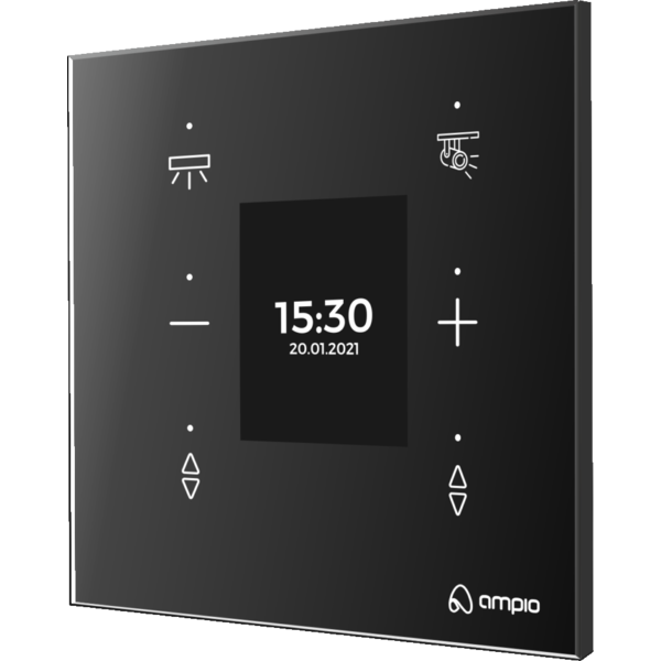
The image above is for illustration purpose only. The actual module may vary from the one presented here.
* The exact dimensions of the module depend on the variant of the glass edge finish selected when placing an order.
Module M-DOT-6 is a component of the Ampio system. Required voltage to power the module is 11 — 16V DC. The module is controlled via CAN bus.
The module has six sensor fields, a display and a 1-Wire interface.
The touch panel sensor fields are capacitive buttons located behind the glass pane, which is the front of the module. Each sensor field is marked with a symbol engraved on the glass surface.
The condition for triggering an action associated with a given field can be pressing, holding, double-pressing, etc. A single field can initiate multiple actions depending on how it is triggered.
Each sensor field is illuminated by an RGB diode, which allows one to define any backlight colour. The backlight can be constant or change during the system operation, signalling the status of devices associated with the field or any other information available in the building automation system.
There are coloured status LEDs above the sensor fields. As in the case of backlight, they can signal the status of devices associated with the field or any other information available in the building automation system.
The brightness of both, the symbols and the status LEDs, can be modified. The panel has a proximity sensor, thanks to which it is possible to define a weaker backlight when there is no interaction with the panel, and a stronger one, which activates when one brings a hand close to the panel.
The M-DOT panel calibration process runs automatically each time the power is switched on. To ensure optimum sensitivity and trouble-free operation of the device, it is essential to follow the guidelines below:
Final installation: Calibration must only be carried out after the panel has been fully installed in the mounting box. Testing the module ‘in your hand’ prior to installation prevents the correct reading of the base electrical capacitance, resulting in unstable operation of the touch panels.
Calibration procedure:
Install the panel in its intended location.
Reset the power supply (by switching it back on).
Note: Do not touch the front of the device for the first 3 seconds after start-up. During this time, the sensors stabilise in relation to the ambient conditions.
The module is equipped with a 2" LCD. There are three sections on the display, which facilitate presenting any information available in the building automation system, e.g. date and time or temperature measurement results.
If the installation includes an IP integration module from the M-SERV family, it is possible to display on the panel information downloaded from the network, e.g. weather, stock information, etc.
The symbols of the module’s sensor fields are engraved in accordance with the client’s design. The colour of the module’s front glass and the chamfer’s width of the glass edge are also subject to personalisation.
The module is equipped with a buzzer that enables generating sound signals. By default, each press of the sensor field triggers a short buzzer sound. However, this behaviour can be modified.
In addition to confirming that the sensor field has been pressed, the buzzer can be used to signal any other events observable by the building automation system. The sound volume and type are defined at the device configuration stage.
The module is equipped with a 1-Wire interface connector that allows to connect up to 6 digital Dallas DS18B20 temperature sensors. The temperature measurement result is available for all devices operating within the building automation bus. It may turn out to be particularly useful for purposes related to temperature regulation, or to present the measurement result on touch panels and in a mobile application.
The total length of the 1-Wire bus cable to which the temperature sensors are connected cannot exceed 15m.
The panel can be mounted on a surface or it can be flush with the wall surface. Depending on the expected effect, a flush mounting plate or surface mounting frame is used. The frames are available in two variants - for panels with glass with and without chamfered edges.
Both in the case of flush and surface mounting, a standard junction box must be located behind the panel, inside which there will be connectors for the CAN bus and the 1-Wire interface. In the case of flush mounting, the box must be embedded in the wall at a greater than standard depth.
A detailed description of the installation of panels in both variants is available in the appropriate installer guides published on the Ampio knowledge base website.
On the back of the device, there is one red LED indicating the communication status within the CAN bus:
After the device is embedded in the mounting plate or frame, the LED is hidden.
The module is programmed with the use of the Ampio Designer software. It allows you to modify the parameters of the module and define its behaviour in response to signals directly available to the module as well as general information coming from all devices present in the home automation bus.
Dimensions expressed in millimeters.
The panel consist of a glass front and a body with connectors and mechanical interfaces meant for mounting with the use of mounting plates or surface frames. The body is mounted in the center of the rear surface of the glass front with a margin of error appropriate for the production process.
The exact dimensions of the module front depend on the variant of the glass edge finish selected when placing an order.
In the dimensions diagram, the dashed line marks the area where the connectors of the device and its other elements protruding from the body are located. The outline of this area corresponds to the central opening in mounting plates and frames for panels. In the actual module, the CAN bus and 1-Wire interface connectors may be located in a different place than in the figure below, but within the marked area.
 Click to enlarge and open in a new tab.
The location of the device connectors on the connection diagram is indicative - in the physical module their location may be different.
