The image above is for illustration purpose only. The actual module may vary from the one presented here.
Module M-IN-2p is a component of the Ampio system. Required voltage to power the module is 11 — 16V DC. The module is controlled via CAN bus.
The module has two ground detecting inputs, a 1-Wire interface and a brightness sensor.
The module has inputs that go into the active state when they are shorted to ground. They can be used in the case of any devices with potential-free contact outputs, e.g. wall switches, reed switches, buttons, switches, etc. They can also be used for integration with devices with potential-free relay outputs or optocoupler outputs with a collector voltage greater than 12V.
The module is equipped with a 1-Wire interface connector that allows to connect up to 6 digital Dallas DS18B20 temperature sensors. The temperature measurement result is available for all devices operating within the building automation bus. It may turn out to be particularly useful for purposes related to temperature regulation, or to present the measurement result on touch panels and in a mobile application.
The total length of the 1-Wire bus cable to which the temperature sensors are connected cannot exceed 15m.
The module is equipped with a brightness sensor. The main purpose of the sensor is to detect the fact that the module has been removed from a junction box. This information can be used to detect unauthorised physical access to the device, especially, when the module is used for signal acquisition in alarm systems.
The dimensions of the module enable its installation in a standard junction box. In order to start the module, it must be connected to the CAN bus. The bus of the Ampio system consists of four wires - two for power and two for communication between the modules.
In addition to the CAN bus, up to two devices with potential-free contact outputs and up to six digital Dallas DS18B20 temperature sensors can be connected to the device.
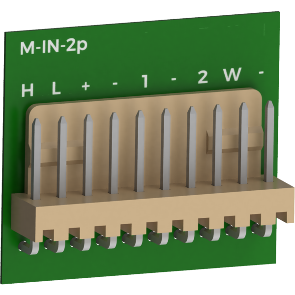
Due to the small dimensions of the device, electrical connections are not made using screw terminals - as is the case with most Ampio system modules - but with a 10-pin connector with a 2.54 mm raster. Each module comes with a plug with mounted wires that allows to connect the device without using a crimping tool.
The M-IN-2p module has no housing, therefore it should be installed in a way that prevents accidental short circuits.
When installing the module, protect the module against accidental short-circuiting between exposed electronic components.
On the device, there is one red LED indicating the communication status within the CAN bus:
The module is programmed with the use of the Ampio Designer software. It allows you to modify the parameters of the module and define its behaviour in response to signals directly available to the module as well as general information coming from all devices present in the home automation bus.
Dimensions expressed in millimeters.
 Click to enlarge and open in a new tab.
