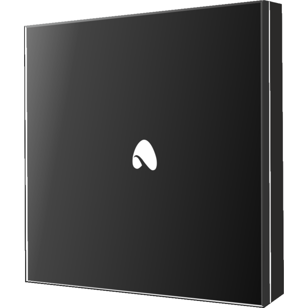
The image above is for illustration purpose only. The actual module may vary from the one presented here.
Module M-SENS-LITE is a component of the Ampio system. Required voltage to power the module is 11 — 16V DC. The module is controlled via CAN bus.
The module allows for the measurement of ambient conditions in closed spaces.
The module facilitates measuring a number of parameters for the environmental conditions present in closed spaces. Measurement results are available for all devices operating within the building automation bus. They may turn out to be particularly useful for purposes related to the regulation of temperature or ventilation of rooms, or for the presentation of measurement results on touch panels and in the Ampio mobile application.
The values measured by the device are:
The device is mounted directly on a wall or any other flat surface. The junction box is not used for the installation. The module consists of two parts - the body and the casing. At the back of the body there are two holes with a diameter of 4mm for mounting the device, and one with a diameter of 10.5mm, which serves as a cable grommet.
After mounting the body onto the wall, one may innstall its casing. The casing assembly is based on a magnetic mechanism.
The module is programmed with the use of the Ampio Designer software. It allows you to modify the parameters of the module and define its behaviour in response to signals directly available to the module as well as general information coming from all devices present in the home automation bus.
For the M-SENS-LITE module to work properly, at least three modules must be available on the bus: M-SENS-LITE and two modules other than those from the M-SENS family.
Dimensions expressed in millimeters.
Click to enlarge and open in a new tab.
In order to show the CAN bus connector, the figure presents only the body of the module without its casing.