The image above is for illustration purpose only. The actual module may vary from the one presented here.
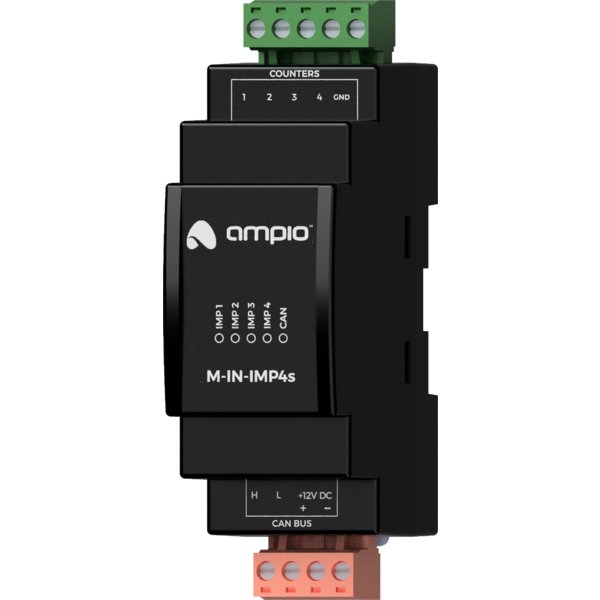
Module M-IN-IMP4s is a component of the Ampio system. Required voltage to power the module is 11 — 16V DC. The module is controlled via CAN bus.
The module is designed for mounting on a 35mm DIN rail. The module’s width is 35mm, 2 spaces/modules in DB. In order to start the module, it must be connected to the CAN bus. The bus of the Ampio system consists of four wires - two for power and two for communication between the modules.
On the front of the module there are signalling LED indicators. The green LED with the label CAN indicates the status of communication on the CAN bus:
In addition to a diode indicating the status of the communication bus, there are four more diodes on the front of the device indicating the counting of pulses from the corresponding inputs.
The module is programmed with the use of the Ampio Designer software. It allows you to modify the parameters of the module and define its behaviour in response to signals directly available to the module as well as general information coming from all devices present in the home automation bus.
In order to enable the module to be connected to an operational meter or to change to a new meter, each of the 4 meter inputs can be reset to zero or given any value. This is possible via the parameters function in the Ampio Designer tool.
Dimensions expressed in millimeters.
 Click to enlarge and open in a new tab.
