The image above is for illustration purpose only. The actual module may vary from the one presented here.
Module M-CON-KEY-p is a component of the Ampio system. Required voltage to power the module is 11 — 16V DC. The module is controlled via CAN bus.
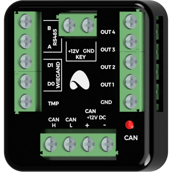
The module has four OC binary outputs.
List of access control modules supported by the M-CON-KEY-p module:
The dimensions of the module enable its installation in a standard junction box. In order to start the module, it must be connected to the CAN bus. The bus of the Ampio system consists of four wires - two for power and two for communication between the modules.
Apart from the CAN bus connector, the device has three connectors with screw terminals. In addition to integration with access control modules, they allow four resistive loads to be connected to the two-state open-collector outputs.
When using the open-collector outputs functionality, it should be borne in mind that the supply circuits of the connected loads are closed by the mass of the module. Therefore, it should be ensured that the mass of the device is connected to the mass of the power supply with a cable of appropriate thickness.
On the front of the module there are signalling LED indicators. The redl LED with the label CAN indicates the status of communication on the CAN bus:
The module is equipped with a tamper contact so that when the appropriate logic is connected and programmed into the module, an attempt to steal the access control module can be detected.
The module is programmed with the use of the Ampio Designer software. It allows you to modify the parameters of the module and define its behaviour in response to signals directly available to the module as well as general information coming from all devices present in the home automation bus.
If the module has a buzzer or PIN_OK contact, it is connected to output number 1 by default, while the electric door strike is connected to output number 4 by default.
Dimensions expressed in millimeters.
The dashed lines mark the areas where the device connectors or its other elements can be located.
 Click to enlarge and open in a new tab.
